Heat dissipation assembly for computing devices

Active Publication Date: 2006-07-13
GUNDERSON H CHRISTIAN +1
View PDF5 Cites 3 Cited by
  • Summary
  • Abstract
  • Description
  • Claims
  • Application Information

AI Technical Summary

Benefits of technology

[0010] The present invention involves an assembly for use in a computing device such as a personal laptop computer, desk top computer, server or video game terminal. Each of these devices includes a microprocessor which generates heat during its operation. The invention includes the use of a heat sink in thermal contact with the microprocessor which is capable of providing a heat dissipating sink for removing thermal energy from the microprocessor much more effectively than devices of the prior art. The present invention includes applying a water barrier proximate the socket employed for making electrical connection to the microprocessor preventing water of condensation from contacting areas covered by the water barrier. Alternatively, the microprocessor can be encased within a shell having a fluid inlet and fluid outlet for recirculating coolant proximate the microprocessor and, if properly configured, the need for a water barrier applied to the socket and surrounding regions can be effectively eliminated. In either case, efficient refrigeration protocols are suggested to maximize heat dissipation.

Problems solved by technology

As speeds increase, microprocessors operate at higher temperatures and, in fact, the single most important limiting factor in inhibiting computing speed is the thermal energy generated from such devices.
However, cooling fans tend to be noisy and thus can represent a significant distraction to a user.
Further, the mere passage of air over a microprocessor contained within the small confines of a personal computer is not a particularly efficient method of dispersing heat energy.
Unless sufficient cooling is carried out, the heat generated by the microprocessor can cause it to overheat and damage the device.
Recognizing that conventional fan-cooled computers represent a distraction and can cause a significant annoyance to a user affecting productivity, there have been attempts to deal with heat dissipation by means other than a fan.
The rather inefficient configuration taught by this reference is intended to reduce condensation that may form when operating at sub-ambient temperatures to reduce the risk of water damage to the interior of the cooled chamber.
Clearly, such a configuration reduces the effectiveness of the heat sink for direct contact between it and the electronic device to be cooled is avoided so as to prevent water of condensation from being created at or around the microprocessor.
Firstly, it is universally accepted that microprocessors, hard disk drives and other active components in a computing device must be cooled for limitations as to speed and computing power are limited by failure to dissipate heat, particularly from a microprocessor.
Secondly, the prior art, although suggesting alternatives to traditional fan-based cooling devices, has suggested either non-optimal heat transfer configurations or limitations in cooling in order to minimize or entirely prevent water of condensation from adversely impacting the microprocessor and its surrounding topology.

Method used


Image

  • Heat dissipation assembly for computing devices
  • Heat dissipation assembly for computing devices
  • Heat dissipation assembly for computing devices

Examples


Embodiment Construction

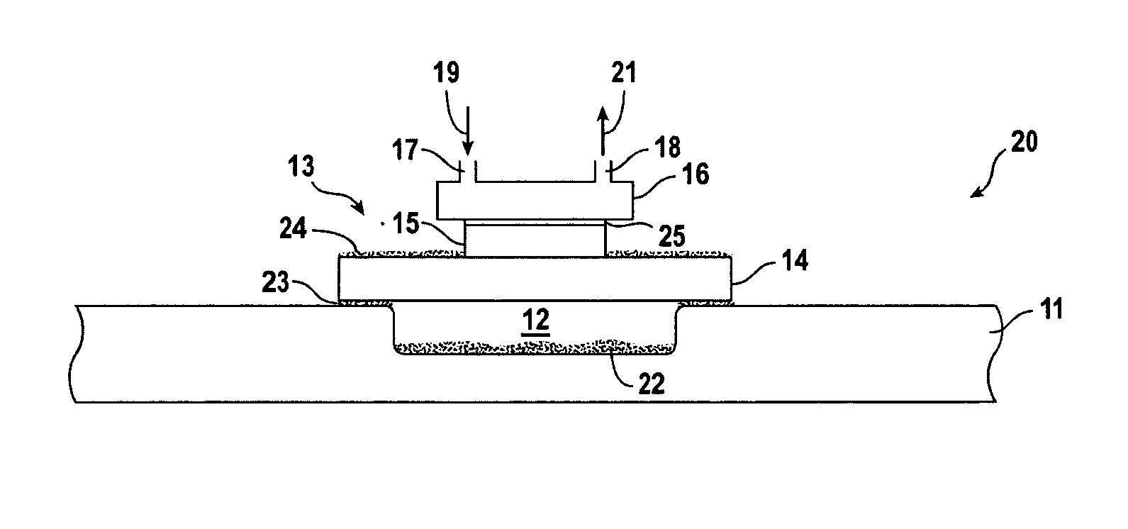
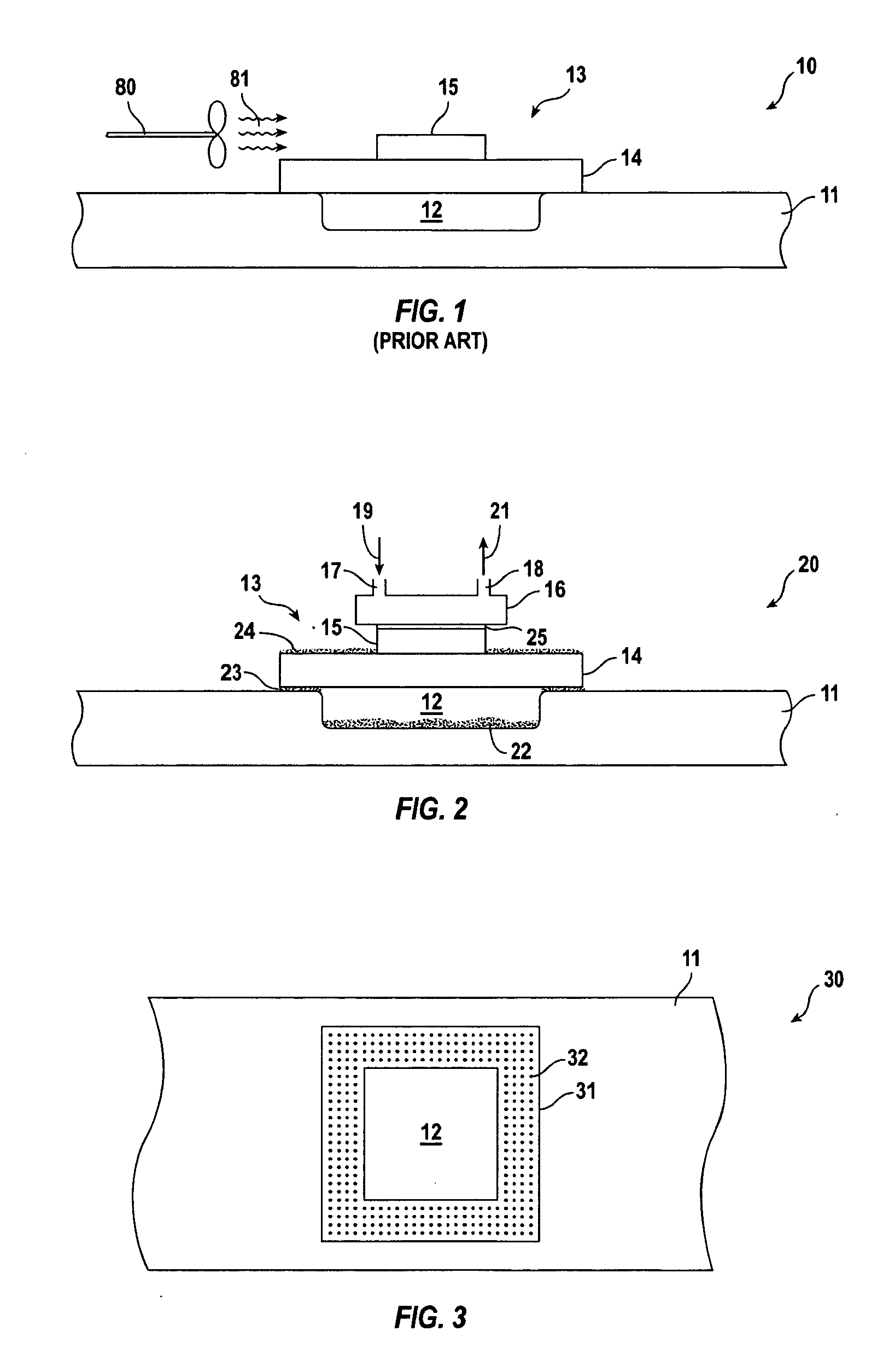
[0015] Turning first to FIG. 1, a cross-sectional view of a relevant area of a computing device 10 is shown. Specifically, motherboard 11 is depicted in partial cross-section supporting a microprocessor CPU 13 consisting of substrate 14 and die 15. Microprocessor CPU 13 can be applied to supporting motherboard 11 either through a pin connection or by a flush connection over indented region 12. That portion of motherboard 11 supporting microprocessor CPU 13 is shown in top plan view in FIG. 3. In this embodiment, pin receiving socket 31 having openings 32 for receiving the pins of substrate 14 (not shown) surrounds indented region 12.

[0016] Turning back to FIG. 1, a schematic depiction of a current cooling method commonly employed in laptop and desk top computers is shown. Specifically, fan 80 is caused to rotate by connecting a shaft to a motor (not shown) which can either be constantly engaged or periodically engaged through activation prompted by a thermo-couple or other thermal ...


PUM


Abstract

Computing devices, including laptop computers, desk top computers, servers and video game terminals employ microprocessors which generate considerable heat. In fact, the heat generated from microprocessors is generally considered the limiting factor in computing speed. A heat sink is provided in thermal contact with a microprocessor whereby a water barrier is applied to and proximate a socket configured within the computing device's motherboard for preventing water of condensation from contacting areas covered by the water barrier.

Description

TECHNICAL FIELD OF INVENTION [0001] Computing devices, including laptop computers, desk top computers, servers and video game terminals employ microprocessors which generate considerable heat. In fact, the heat generated from microprocessors is generally considered the limiting factor in computing speed. A heat sink is provided in thermal contact with a microprocessor in cooperation with a water barrier applied to and proximate a socket configured within the computing device's motherboard for preventing water of condensation from contacting areas covered by the water barrier. Efficient refrigeration protocols are suggested to maximize heat dissipation. BACKGROUND OF THE INVENTION [0002] As computing devices have become more powerful, microprocessor integrated circuits have become more sophisticated having increased clock speeds and computing power. As speeds increase, microprocessors operate at higher temperatures and, in fact, the single most important limiting factor in inhibiting...

Claims


Application Information

Patent Timeline
IPC IPC(8): H05K7/20
CPCG06F1/20H01L23/473H05K7/20772H01L2924/0002H01L2924/00
Inventor COHEN, ALAN MARK
Owner GUNDERSON H CHRISTIAN
Why Eureka
Try Eureka