Water chiller economizer system

a water chiller and economizer technology, applied in the field of refrigeration systems, can solve the problems of large refrigeration systems that often require significant chilling capacity, large compressors which tend to be inefficient and costly, and large operational costs

Active Publication Date: 2007-10-18
KING MARTIN P
View PDF24 Cites 13 Cited by
  • Summary
  • Abstract
  • Description
  • Claims
  • Application Information

AI Technical Summary

Benefits of technology

[0011] According to one aspect, the present invention provides a process-fluid chiller system for chilling a process fluid to be transported to a process load to remove thermal energy from the process load. The process-fluid chiller system includes a storage tank in which the process fluid can be stored, and a refrigeration system that can be selectively activated to chill the process fluid. The refrigeration system includes an evaporation device for evaporating a refrigerant from a liquid state to a gaseous state and a compressor for elevating a pressure of the refrigerant in the gaseous state. A temperature sensor is included for sensing a temperature of an exchange medium to which thermal energy from the process fluid can be transferred when the temperature of the exchange medium falls below a predetermined low temperature. Also included is a closed-loop heat exchanger that can selectively be placed in fluid communication with the storage tank and selectively taken out of fluid communication with the storage tank based at least in part on the sensed temperature of the exchange medium. The process-fluid chiller system further includes a control system for controlling activation of the refrigeration system and selective placement of the closed-loop heat exchanger in fluid communication with the storage tank.

Problems solved by technology

Large refrigeration systems often demand significant chilling capacity to provide a sufficient amount of chilled fluid to adequately cool large processes and process equipment operating at very high temperatures.
To meet such demands the refrigeration system discussed above requires large compressors which tend to be inefficient and costly.
Further, these compressors must be continuously operated to satisfy chilling demands, leading to large operational costs.
The airflow causes at least some of the water to evaporate, thereby chilling the water as it flows through the cooling tower.
However, cooling towers are limited in their ability to adequately chill water based on the temperature and relative humidity in their ambient environment.
This prohibits the use of cooling towers as options for chilling water or other process fluids in many geographic regions.
Further, processes that utilize water directly from a cooling tower to cool process equipment typically require the water to be conditioned to remove foreign matter collected from the water while it was exposed to the ambient environment during cooling before being transported to the equipment to be cooled.

Method used


Image

  • Water chiller economizer system
  • Water chiller economizer system
  • Water chiller economizer system

Examples


Embodiment Construction

[0024] Certain terminology is used herein for convenience only and is not to be taken as a limitation on the present invention. Relative language used herein is best understood with reference to the drawings, in which like numerals are used to identify like or similar items. Further, in the drawings, certain features may be shown in somewhat schematic form.

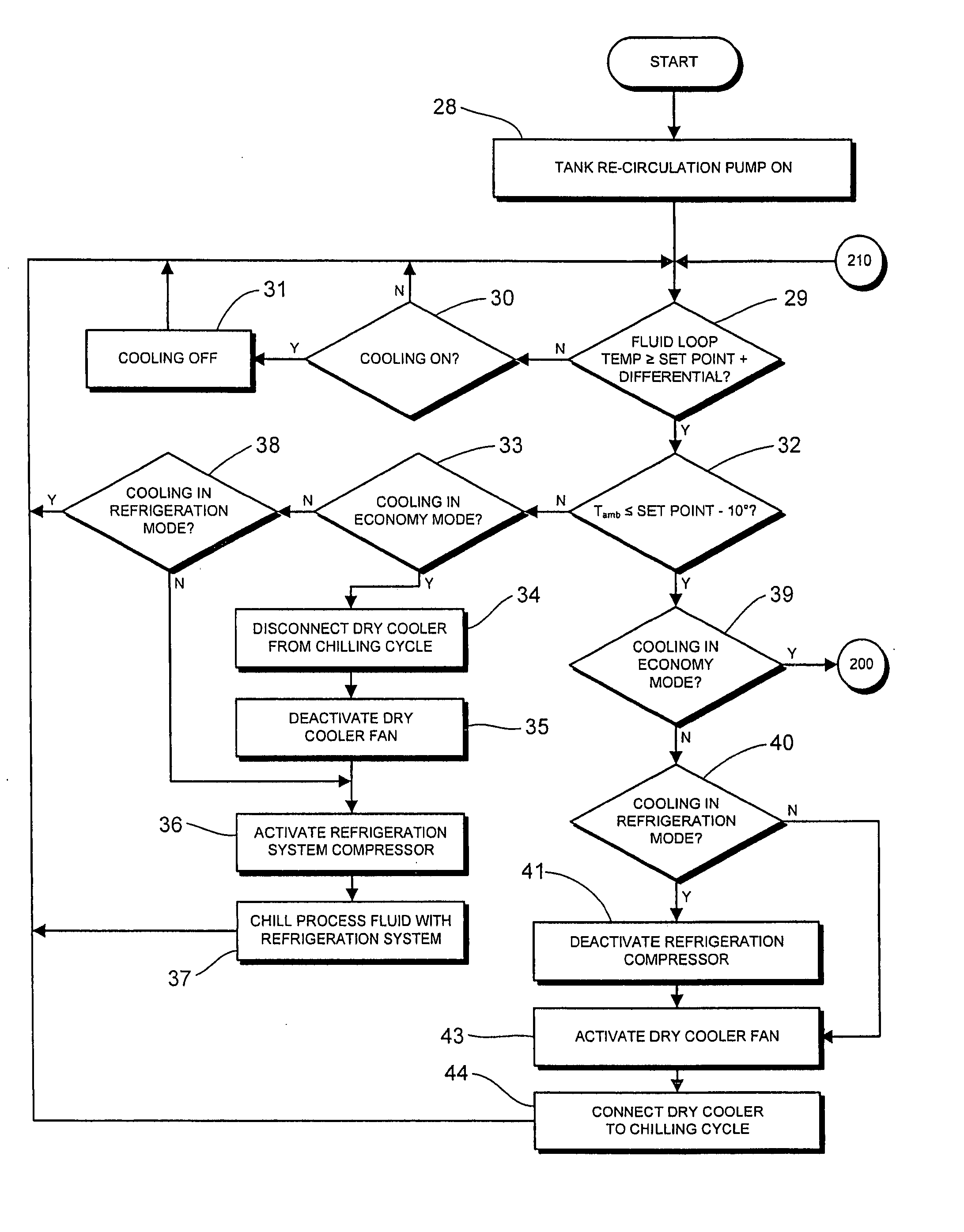
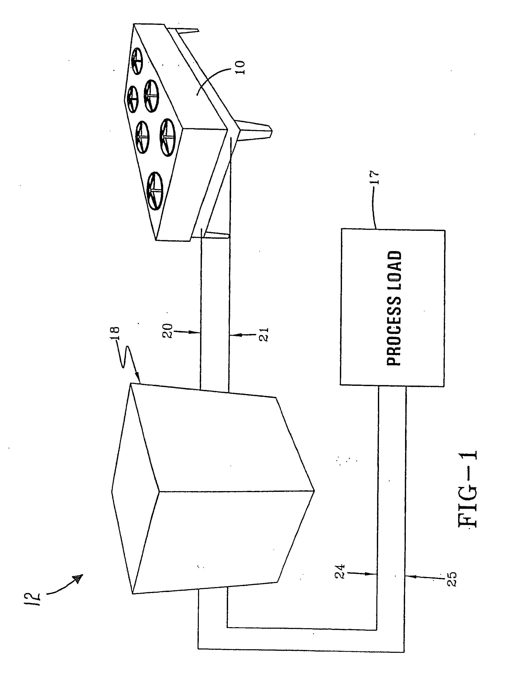
[0025]FIG. 1 shows a perspective view of an illustrative embodiment of a process fluid chiller system 12 according to the present invention. As shown, the chiller system 12 includes a refrigeration-based process chiller 18 and a dry cooler 10 that can cooperate or operate as alternatives to chill a process fluid for cooling a process load 17. The process load 17 can be a warm environment that requires cooling, one or more pieces of process equipment or hardware included as part of an industrial, commercial or other type of process. The process load 17 can be cooled by introducing the chilled process fluid directly into a cavity o...


PUM


Abstract

A process-fluid chiller system for chilling a process fluid to be transported to a process load to remove thermal energy from the process load. The process-fluid chiller system includes a storage tank in which the process fluid can be stored, and a refrigeration system that can be selectively activated to chill the process fluid. The refrigeration system includes an evaporation device for evaporating a refrigerant from a liquid state to a gaseous state and a compressor for elevating a pressure of the refrigerant in the gaseous state. A temperature sensor is included for sensing a temperature of an exchange medium to which thermal energy from the process fluid can be transferred when the temperature of the exchange medium falls below a predetermined low temperature. Also included is a closed-loop heat exchanger that can selectively be placed in fluid communication with the storage tank and selectively taken out of fluid communication with the storage tank based at least in part on the sensed temperature of the exchange medium. The process-fluid chiller system further includes a control system for controlling activation of the refrigeration system and selective placement of the closed-loop heat exchanger in fluid communication with the storage tank.

Description

CROSS-REFERENCE TO RELATED APPLICATIONS [0001] This application claims the benefit of U.S. Provisional Application No. 60 / 792,778, filed on Apr. 17, 2006 entitled Water Chiller Economizer System.BACKGROUND OF THE INVENTION [0002] 1. Field of the Invention [0003] This invention relates generally to the field of refrigeration systems, and more particularly to an electronically-controlled process fluid chilling system including a chiller and a dry cooler providing a heat exchange between an exchange medium and the process fluid flowing through the dry cooler. And even more particularly, embodiments of the present invention also relate to a microprocessor-based controller for implementing the system. [0004] 2. Description of Related Art [0005] Conventional refrigeration systems utilize a refrigerant that removes heat from a fluid used for cooling applications and ejects the removed heat to a heat sink in an ambient environment of the refrigeration system. The heat sink can be ambient ai...

Claims


Application Information

Patent Timeline
Patent Type & Authority Applications(United States)
IPC IPC(8): F25D17/02F25B49/00
CPCF25B2400/24F25B2700/2106F28F27/00F25D17/02F25D16/00
Inventor KING, MARTIN P.
Owner KING MARTIN P
Why Eureka
Try Eureka