Spatial hashing for enhanced control channel search spaces

a search space and enhanced control technology, applied in the field of spatial hashing for enhanced control channel search space, can solve the problems of prohibitively high number of blind decoding attempts for ue and need to limit blind decoding somehow, and achieve the effect of enhancing control channel search spa

Inactive Publication Date: 2013-03-07
AVAGO TECH WIRELESS IP SINGAPORE PTE
View PDF4 Cites 62 Cited by
  • Summary
  • Abstract
  • Description
  • Claims
  • Application Information

AI Technical Summary

Benefits of technology

[0046]It is an object of the present invention to provide an apparatus and method and a computer program product for spatial hashing for enhanced control channel search spaces.

Problems solved by technology

Obviously, such blind decoding needs to be limited somehow in order to avoid excessive UE decoding complexity and latency in decoding control information.
The search space of a single UE obviously cannot span the full CCE space as this would mean prohibitively high number of blind decoding attempts for the UE.
Especially difficult from blocking perspective are UEs scheduled on high aggregation levels.

Method used


Image

  • Spatial hashing for enhanced control channel search spaces
  • Spatial hashing for enhanced control channel search spaces
  • Spatial hashing for enhanced control channel search spaces

Examples


embodiment 1

Tree Structure-Based Spatial Hashing

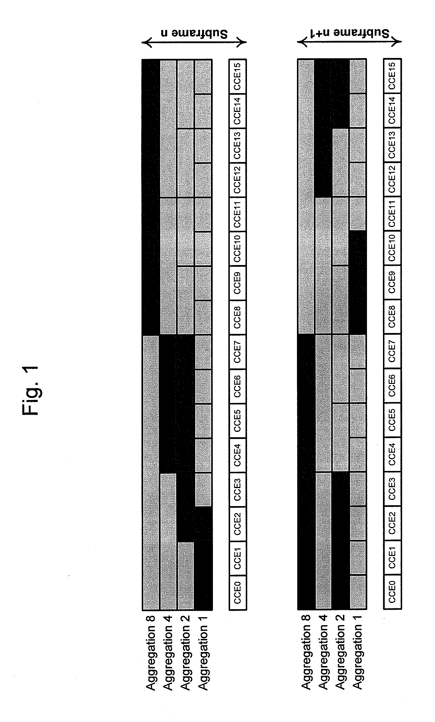
[0132]In the first embodiment, the spatial hashing is done such that for each CCE the UE only needs to estimate channels from one DM-RS port. This is achieved such that the search space locations corresponding to each DM-RS port are fully non-overlapping. As an example, expanding the example of FIG. 1 to multiple DM-RS ports, one might assign separate parts of the overall CCE space to different DM-RS ports to achieve this. In the example of FIG. 2, the CCEs in the second half are decoded based on antenna port 7 and CCEs in the first half of the overall CCE space are decoded based on antenna port 8. The benefit of the method is obviously reduced channel estimation complexity while both ports 7 and 8 are enabled at least in some part of the search space allowing flexibility for scheduling ePDCCH in MU-MIMO over orthogonal DM-RS ports.

embodiment 2

Space-Time Hashing Function

[0133]In the second embodiment, instead of having the search space locations changed in every subframe, as described in the first embodiment, the overall search space locations are changed only every N subframes in case N DM-RS ports are in use. Then, within the N subframes, the search space locations are alternated between the N DM-RS ports. The overall search space is split into N subsets, and in each of the N subframes each DM-RS port is associated with a different subset of the search space locations. It is noted that the subsets are fully non-overlapping (or disjoint), as described above. However, alternatively, it is also possible that the subsets are partially overlapping (or not disjoint).

[0134]FIG. 3 illustrates the idea with N=2. Hence, the full search space is divided into two subsets. In subframe n, antenna port 7 is associated with the first subset and antenna port 8 with the second subset, and in subframe n+1 the association is vice versa.

embodiment 3

Independent Hashing for Each DM-RS Port

[0135]In the third embodiment of the present invention, there are separate search spaces defined for all DM-RS ports, and hashing is DM-RS port-specific. This results in completely independent search spaces associated with each DM-RS port, which is illustrated in FIG. 4.


PUM


Abstract

The present invention provides a method, apparatus and a computer program product for spatial hashing for enhanced control channel search spaces. The present invention includes defining a control channel search space for searching for control channel candidates, defining search space locations within the search space, grouping the search space locations into a plurality of subsets of search space locations, associating each subset of search space locations with an antenna port, for each of a plurality of subframes, changing the search space locations from a first subset of search space locations to a second subset of search space locations.

Description

TECHNICAL FIELD[0001]The present application relates generally to an apparatus and method and a computer program product for spatial hashing for enhanced control channel search spaces.[0002]Currently, Release 10 of the 3rd Generation Partnership Project (3GPP) Long Term Evolution (LTE) specification work starts to be in its final stages. It includes several new features related to downlink and uplink MIMO, relays, bandwidth extension via carrier aggregation and enhanced inter-cell interference coordination (eICIC).[0003]In the meantime, 3GPP has also started working on the next release of the LTE specifications, i.e. Release 11. One ongoing Study Item there is downlink MIMO enhancements, one topic of which is downlink control signaling enhancements. Current downlink control signaling is based on common reference signals which are not precoded and are broadcast all over the cell. When multiple antennas are in use at an evolved NodeB (eNodeB), transmit diversity is applied, for exampl...

Claims


Application Information

Patent Timeline
Patent Type & Authority Applications(United States)
IPC IPC(8): H04W4/00
CPCH04L5/0053H04L1/0046
Inventor KOIVISTO, TOMMIROMAN, TIMOENESCU, MIHAI
Owner AVAGO TECH WIRELESS IP SINGAPORE PTE
Why Eureka
Try Eureka