Pressure vessel safety lock apparatus

a technology for locking apparatus and pressure vessels, applied in mechanical equipment, packaging, transportation and packaging, etc., can solve problems such as safety concerns, and achieve the effect of reducing the ability to open the hatch

Active Publication Date: 2013-03-14
ALLREDI LLC
View PDF14 Cites 18 Cited by
  • Summary
  • Abstract
  • Description
  • Claims
  • Application Information

AI Technical Summary

Benefits of technology

[0004]The present apparatus provides an automatic safety lock responsive to internal pressure in a pressure vessel or pressurized tank to minimize the ability to open the hatch before the internal pressure has dropped below a desired threshold. In some aspects, the present disclosure provides a locking device for restricting access to a hatch of a pressure vessel, comprising: a first half portion and a second half portion mounted to each other at rearward ends and configurable between an open configuration and a closed configuration wherein in the closed configuration the first half portion and the second half portion are arranged to prevent the hatch of a pressure vessel from being opened; a pressure-responsive locking member comprising a cylinder assembly having a body portion and a reciprocating cylinder rod that is extendable from a retracted position to an extended position; wherein the pressure-response locking member fluidly communicates with an outlet port of the pressure vessel; and wherein the pressure-responsive locking member is arranged to automatically extend to retain the first and second half portions in the closed configuration when the pressure inside of the pressure vessel is above a predetermined threshold. In some embodiments, the locking device further comprises a latch plate that is pivotally mounted to said first half portion and configurable between an unlatched position and a latched position; wherein the latched position of the latch plate is arranged to retain the first and second half portions in the closed configuration; and wherein the pressure-responsive locking member is arranged to retain the first and second half portions in the closed configuration by preventing the latch plate from changing to an unlatched position.

Problems solved by technology

While such hatches typically have locking mechanisms, there can be safety concerns if the locks are prematurely disengaged while the vessel is still pressurized.

Method used


Image

  • Pressure vessel safety lock apparatus
  • Pressure vessel safety lock apparatus
  • Pressure vessel safety lock apparatus

Examples


Embodiment Construction

[0018]For the purposes of promoting an understanding of the principles of the invention, reference will now be made to the embodiments illustrated in the drawings and specific language will be used to describe the same. It will nevertheless be understood that no limitation of the scope of the invention is thereby intended, such alterations and further modifications in the illustrated device, and such further applications of the principles of the invention as illustrated therein being contemplated as would normally occur to one skilled in the art to which the invention relates.

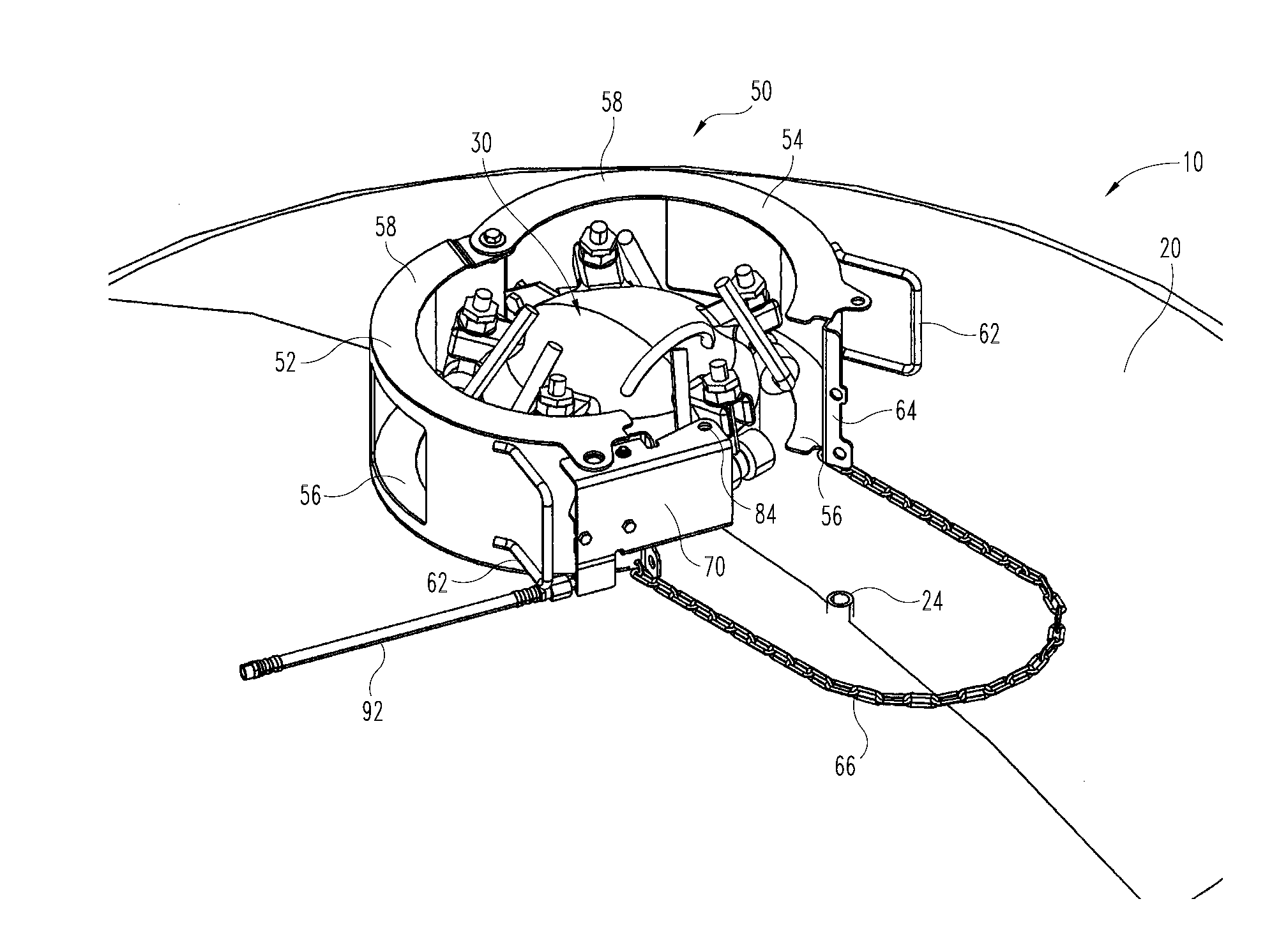
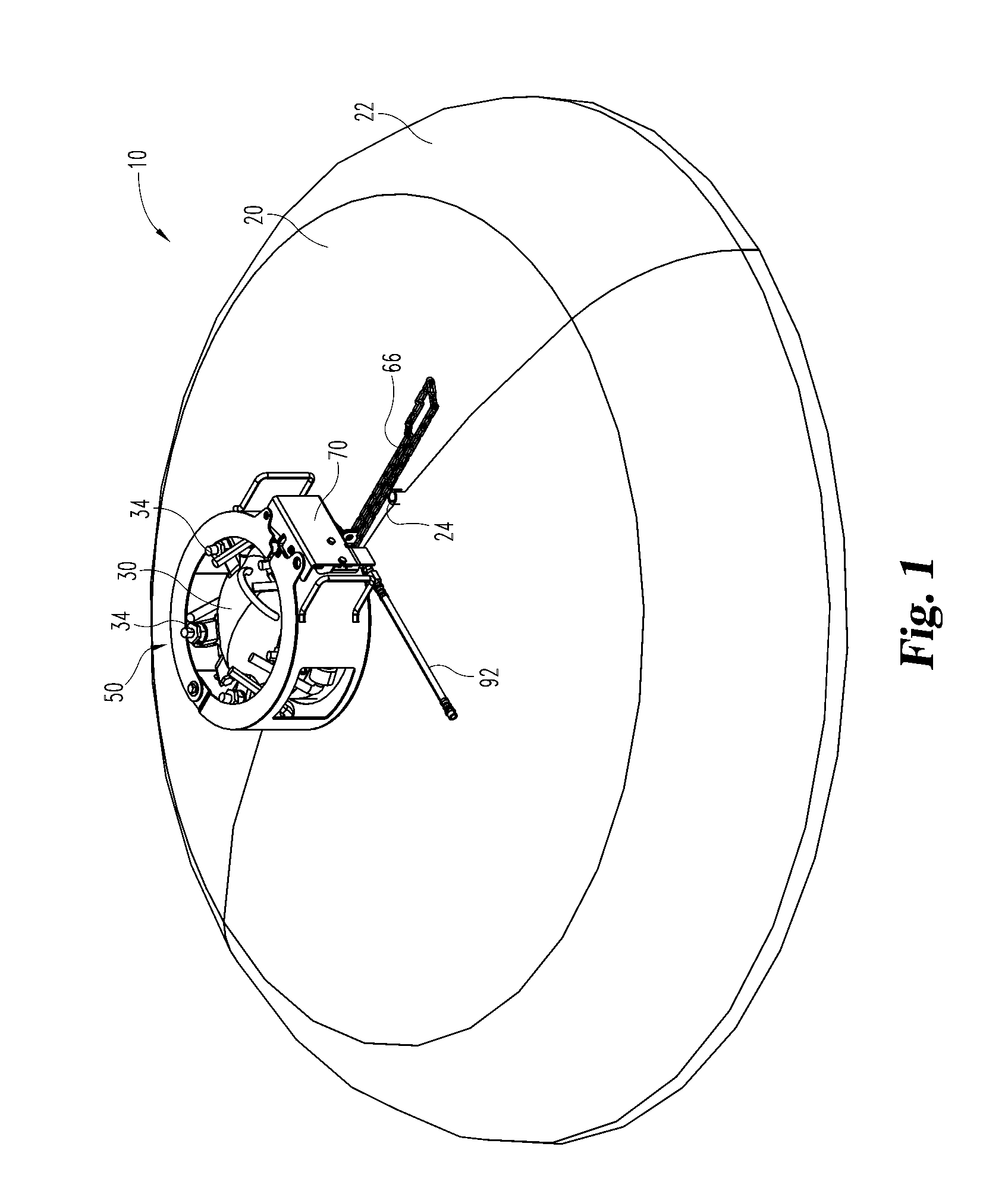
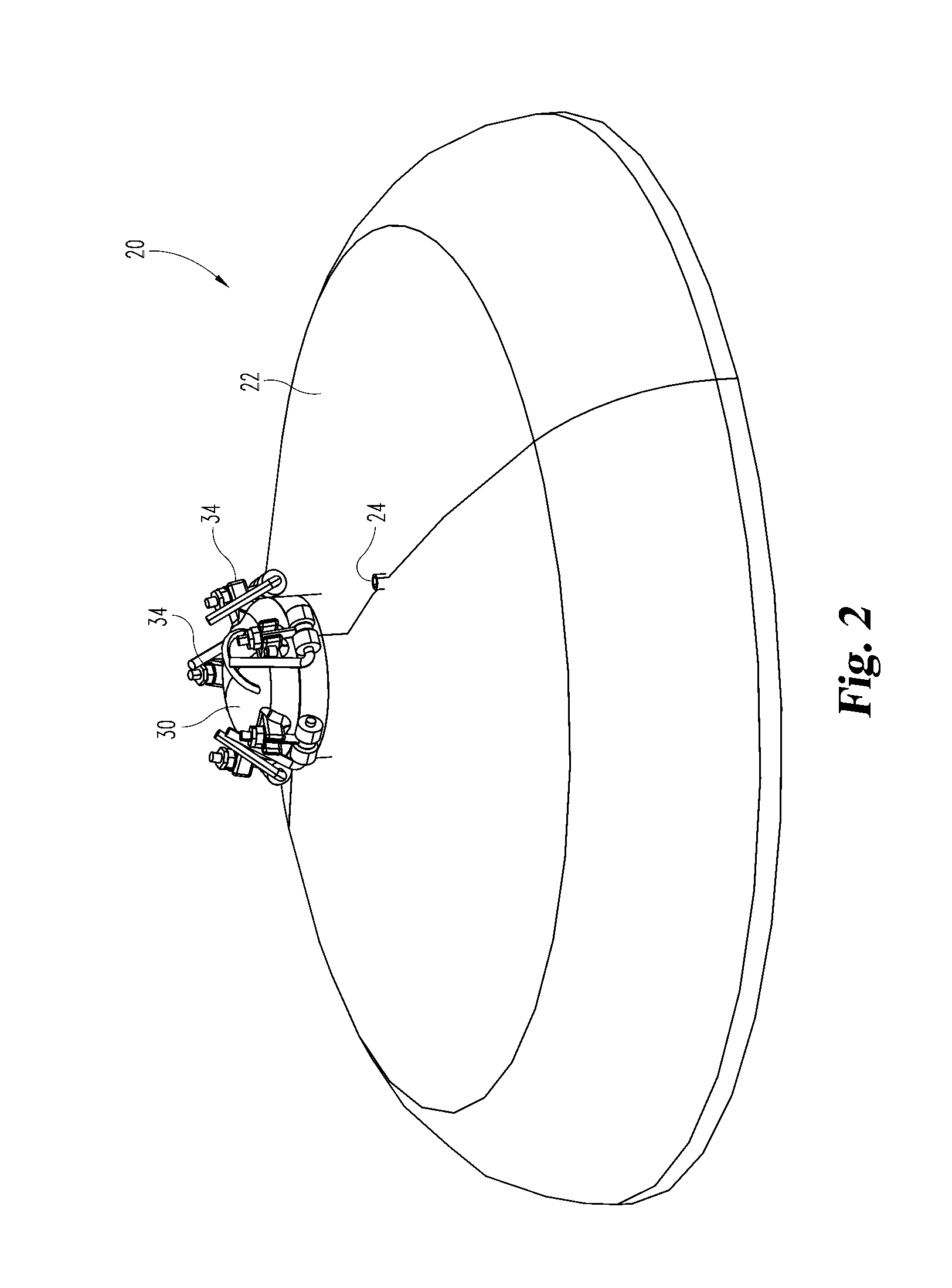
[0019]Pressure vessels for various purposes such as abrasive blasting typically have a fill hatch which is closed and locked when the vessel is under pressure, but which can be opened to add material to the pressure vessel and / or for interior inspection and work. In the drawings provided, the top of a pressure vessel or tank is shown with a hinged hatch which can be locked in a closed position using a set of ca...


PUM


Abstract

The present disclosure provides a locking device for restricting access to a hatch of a pressure vessel, and, more specifically, a locking device that is responsive to the internal pressure in the pressure vessel so as to minimize the ability of one to open the hatch while the vessel is still pressurized. In some embodiments, the locking device comprises first and second portions of the locking device configurable between an open and a closed configuration and a pressure-responsive locking member in fluid communication with an outlet port of the pressure vessel and arranged to automatically retain the first and second portions in the closed configuration when the pressure inside of the pressure vessel is above a predetermined threshold, wherein in the closed configuration the first and second portions restrict manipulation of the hatch and/or a locking mechanism of the hatch.

Description

CROSS-REFERENCE TO RELATED APPLICATION[0001]This application claims the benefit of U.S. Provisional Application No. 61 / 532,243 filed Sep. 8, 2011, which is hereby incorporated by reference.FIELD OF THE INVENTION[0002]Aspects of the present disclosure deal with locking apparatus on pressure vessels.BACKGROUND OF THE INVENTION[0003]Pressure vessels for various purposes such as abrasive blasting typically have a fill hatch which is closed and locked when the vessel is under pressure, but which can be opened to add material to the pressure vessel and / or for interior inspection and work. While such hatches typically have locking mechanisms, there can be safety concerns if the locks are prematurely disengaged while the vessel is still pressurized. The present apparatus provides an automatic safety lock responsive to internal pressure in a pressure vessel or pressurized tank to minimize the ability to prematurely open the hatch.SUMMARY OF THE INVENTION[0004]The present apparatus provides a...

Claims


Application Information

Patent Timeline
Patent Type & Authority Applications(United States)
IPC IPC(8): B65D45/34E05B65/00
CPCE05B51/02F16J13/24E05C19/18E05B65/001Y10T292/20Y10T292/205Y10T292/212Y10T292/228
Inventor MCLAUGHLIN, RICHARDLAFRENZ, CLIFFGRAMLING, CHRIS
Owner ALLREDI LLC
Why Eureka
Try Eureka