
Method For Securing A Stop Member To A Seal Plate Configured For Use With An Electrosurgical Instrument

a technology for sealing plates and electrosurgical instruments, applied in the direction of surgical forceps, manufacturing tools, surgery, etc., can solve the problems of increasing the manufacturing cost of seal plates, complicated techniques, and overall manufacturing costs of electrosurgical instruments

Inactive Publication Date: 2013-03-21
TYCO HEALTHCARE GRP LP
View PDF2 Cites 101 Cited by
  • Summary
  • Abstract
  • Description
  • Claims
  • Application Information

AI Technical Summary

Benefits of technology

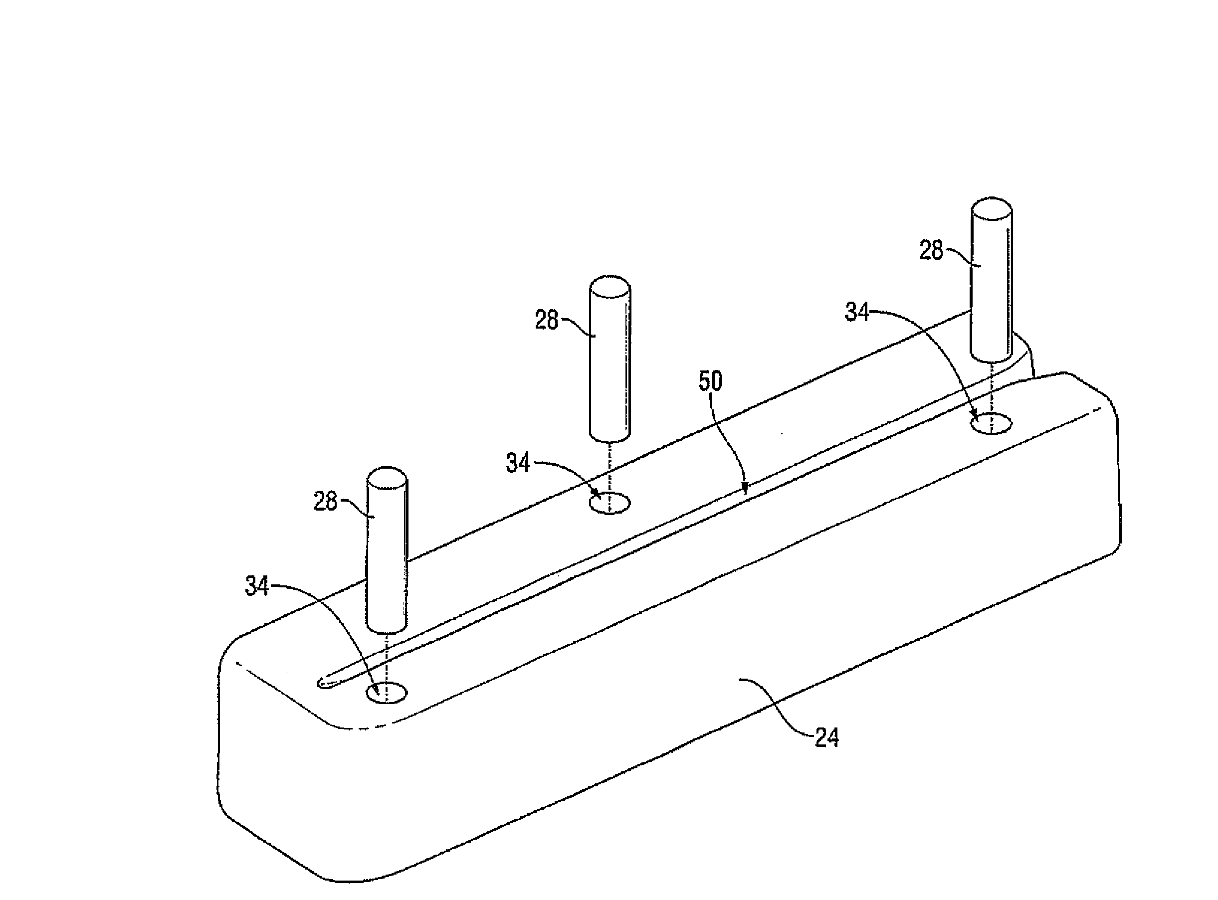
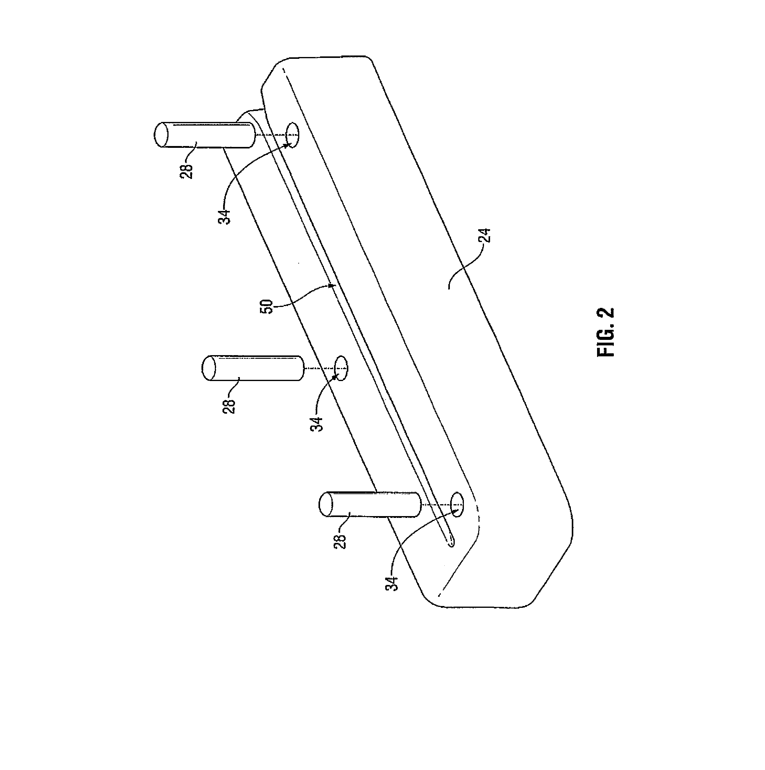
The present patent provides methods for affixing a stop member to a seal plate used in electrosurgical instruments. The stop member is secured within an aperture in the seal plate, which can be formed during a molding process. The stop member can be made from ceramic and can have a higher height than the seal plate. The method also includes positioning a hard stop feature within the aperture to secure the stop member. The seal plate can be heated to shrink and secure the stop member, and the stop member can extend beyond the seal surface of the seal plate. This allows for precise control of the gap distance between electrosurgical jaws.

Problems solved by technology

However, this technique is typically complicated and requires specialty equipment / processes that increase the manufacturing cost of the seal plates, and, thus, the overall manufacturing costs of the electrosurgical instrument.
Moreover, the stop member may be vulnerable to shear stress failure due to the nature of the adhesive.
That is, there exists the possibility of the adhesive not curing properly and succumbing to the shear stresses that may be present during an electrosurgical process, i.e., during the grasping and subsequent sealing of tissue.

Method used


Image

  • Method For Securing A Stop Member To A Seal Plate Configured For Use With An Electrosurgical Instrument
  • Method For Securing A Stop Member To A Seal Plate Configured For Use With An Electrosurgical Instrument
  • Method For Securing A Stop Member To A Seal Plate Configured For Use With An Electrosurgical Instrument

Examples


Embodiment Construction

[0032]Detailed embodiments of the present disclosure are disclosed herein; however, the disclosed embodiments are merely examples of the disclosure, which may be embodied in various forms. Therefore, specific structural and functional details disclosed herein are not to be interpreted as limiting, but merely as a basis for the claims and as a representative basis for teaching one skilled in the art to variously employ the present disclosure in virtually any appropriately detailed structure.

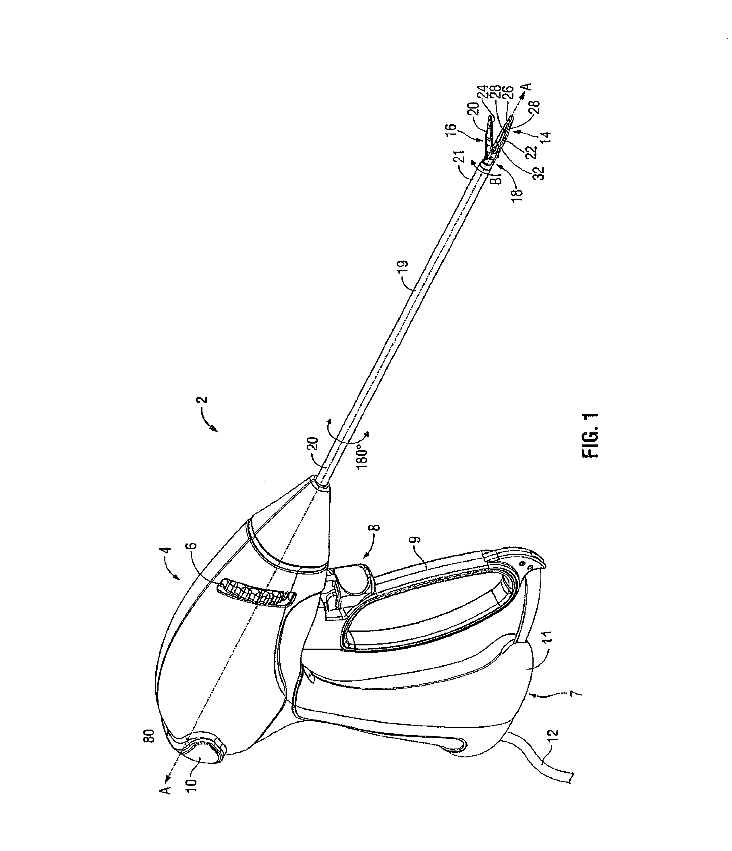
[0033]In the drawings and in the descriptions that follow, the term “proximal,” as is traditional, will refer to an end of a surgical instrument that is closer to the user, while the term “distal” will refer to an end of the surgical instrument that is farther from the user.

[0034]In accordance with the instant disclosure, a unique method of securing a “gap setting feature,” e.g., a stop member, to a seal plate is described herein. The method includes securing a stop member to a seal plate manufact...


PUM

PropertyMeasurementUnit
heightaaaaaaaaaa
heightaaaaaaaaaa
heightaaaaaaaaaa

Abstract

A method for affixing a stop member to a seal plate for use with electrosurgical instruments is provided. An aperture is formed on a seal plate during a metal injection molding process thereof. A stop member is positioned within the aperture on the seal plate. The seal plate is, subsequently, sintered with the stop member positioned in the aperture.

Description

BACKGROUND[0001]1. Technical Field[0002]The present disclosure relates to a method for securing a stop member to a seal plate for use with an electrosurgical instrument. More particularly, the present disclosure relates to securing a stop member to a seal plate manufactured via a metal injection molded manufacturing process.[0003]2. Description of Related Art[0004]Electrosurgical instruments, e.g., endoscopic forceps, are well known in the medical arts. In most instances, the electrosurgical instrument includes a housing, a handle assembly including a movable handle, a shaft and an end effector assembly attached to a distal end of the shaft. The end effector includes jaw members configured to manipulate tissue (e.g., grasp and seal tissue); one (monopolar forceps) or both (bipolar forceps) of the jaw members, typically, include respective seal plates. Typically, the endoscopic forceps utilizes both mechanical clamping action and electrical energy to effect hemostasis by heating the ...

Claims


Application Information

Patent Timeline
Patent Type & Authority Applications(United States)
IPC IPC(8): B22F7/08B23P11/00
CPCB22F3/225B22F7/08A61B18/1445Y10T29/49826A61B2018/0063A61B2019/304A61B2017/00526A61B2090/034
Inventor FRY, MONTE S.
Owner TYCO HEALTHCARE GRP LP
Learn More