
Pneumatic Tire

a technology of pneumatic tires and protrusions, which is applied in the field of pneumatic tires, can solve the problems difficult to achieve the effect difficulty in obtaining the effect of turbulent air flow, so as to achieve the effect of reducing the air resistance of the vehicle, reducing the volume of disposed rubber, and reducing the amount of disposed rubber

Active Publication Date: 2013-03-28
THE YOKOHAMA RUBBER CO LTD
View PDF9 Cites 4 Cited by
  • Summary
  • Abstract
  • Description
  • Claims
  • Application Information

AI Technical Summary

Benefits of technology

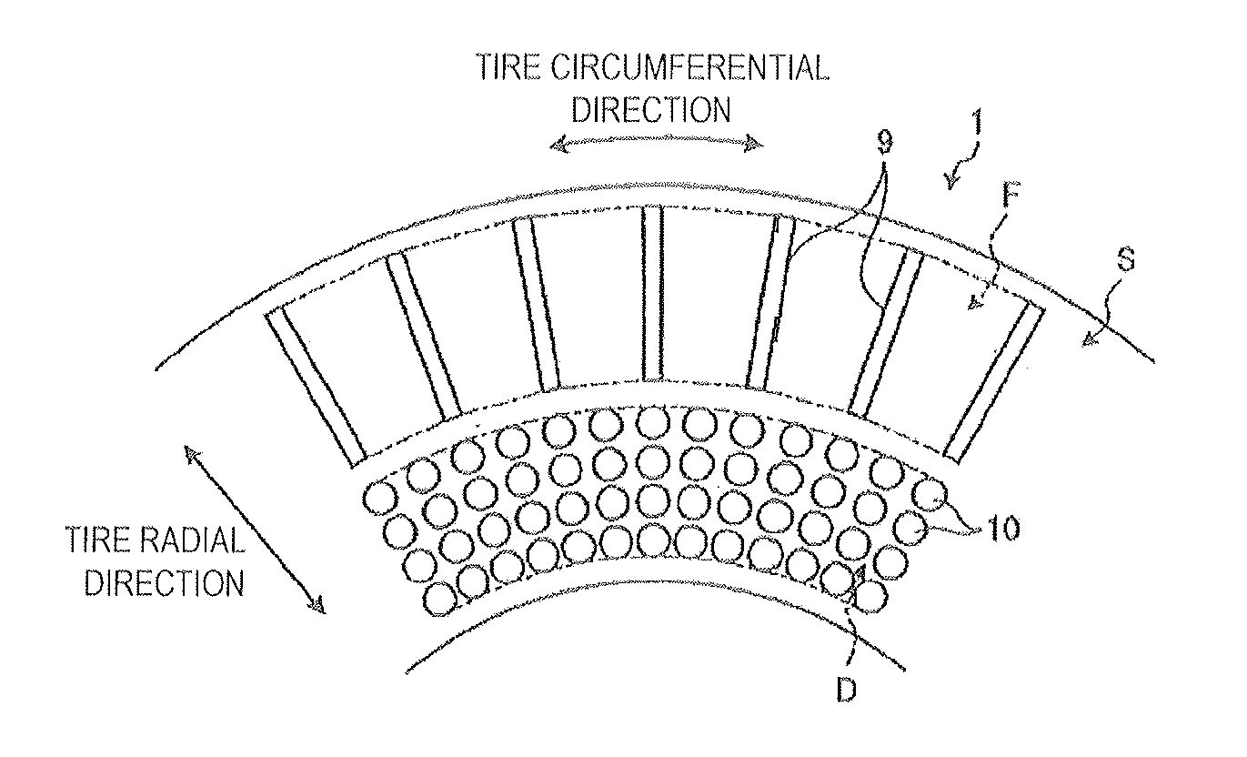
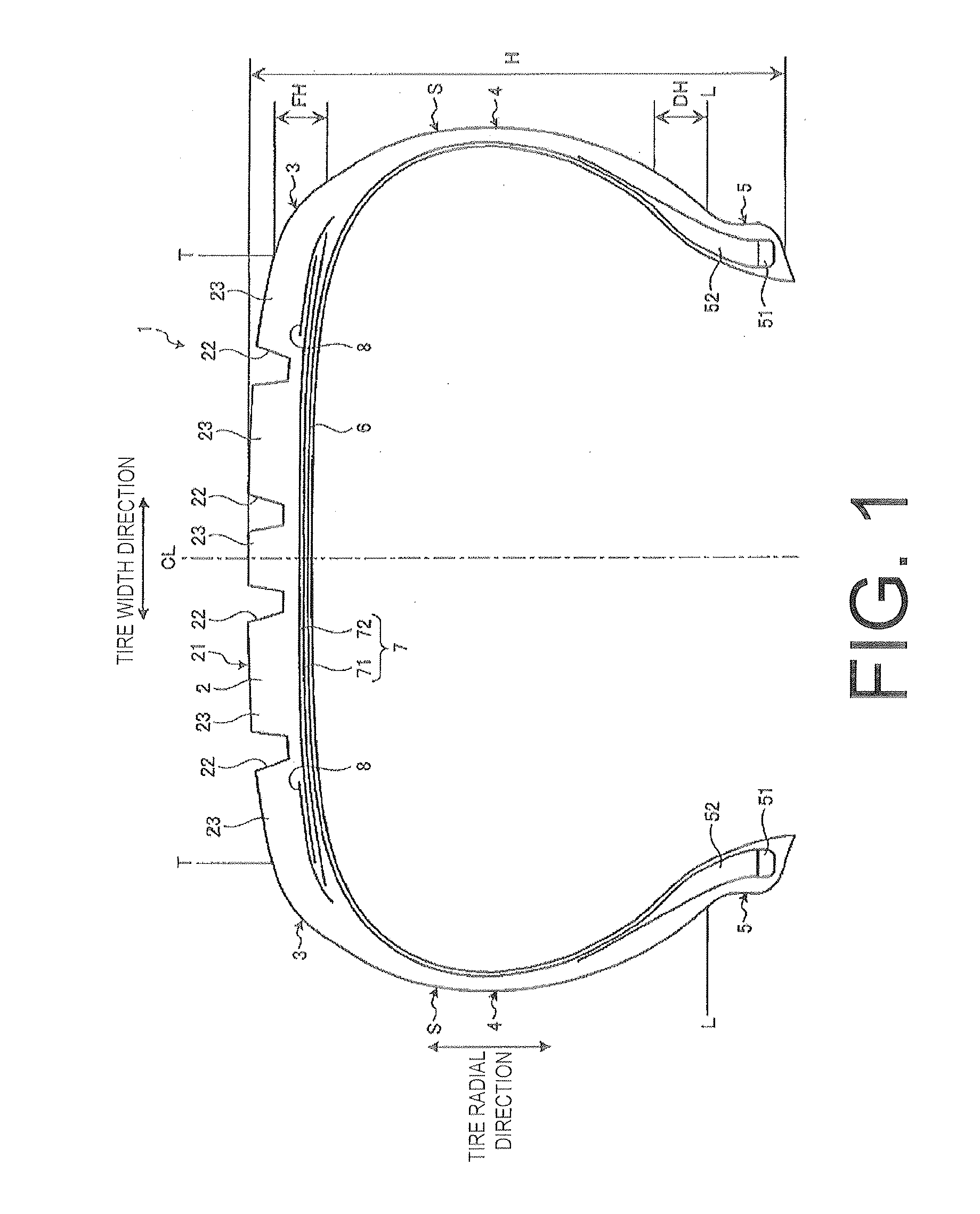
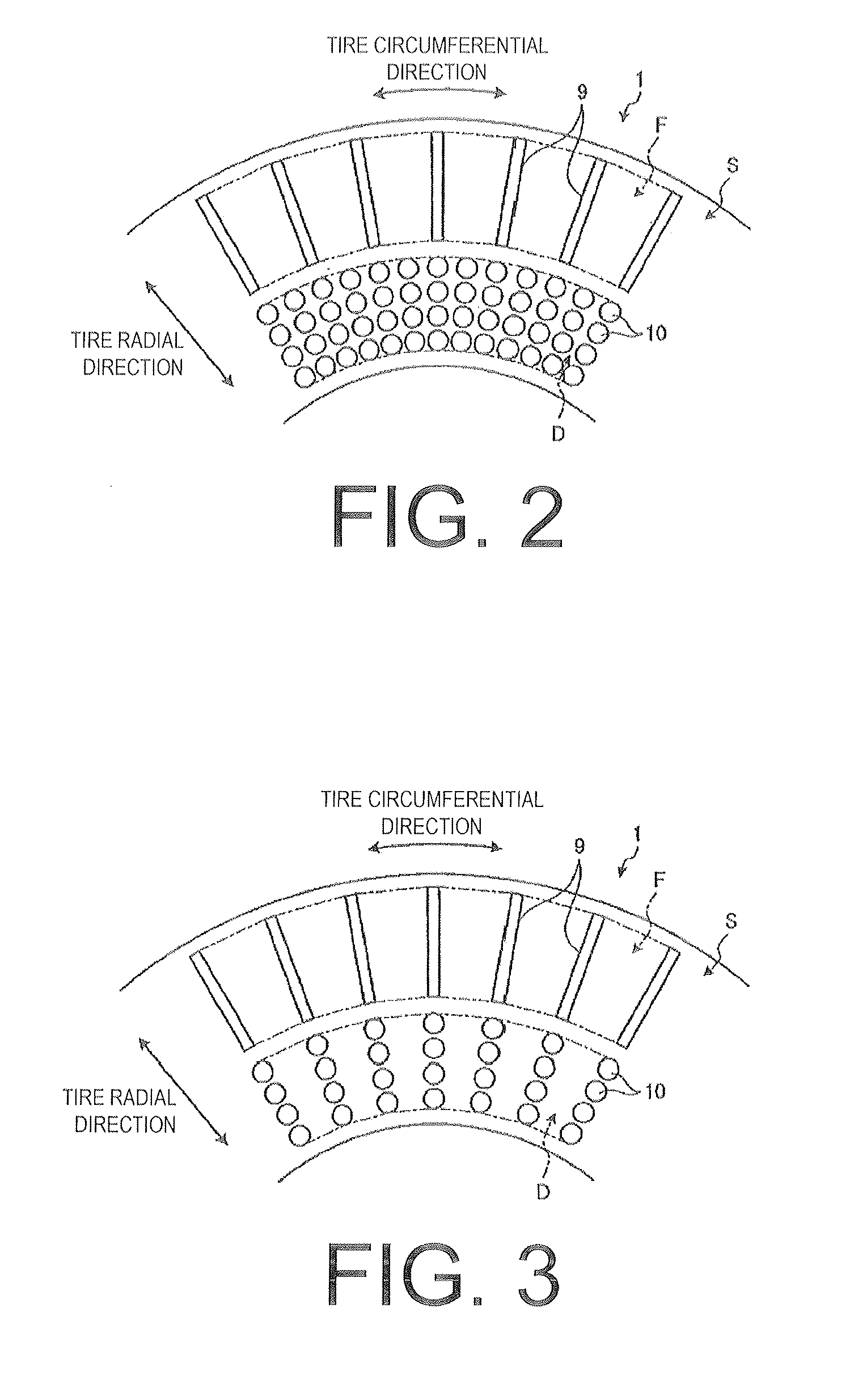
The pneumatic tire described in this patent improves air flow around the tire by creating a turbulent flow boundary layer in the region with protrusions on the outer side of the tire and reducing rubber volume in the region with recesses on the inner side. This results in reduced air resistance, improved fuel economy, and reduced tire heat buildup and temperature increases. Overall, the pneumatic tire improves air flow and enhances the tire's performance.

Problems solved by technology

If the longitudinal direction dimension of the protrusions is less than 5 mm, it will be difficult to obtain the effect of making the air turbulent by the protrusions.
If the height of the protrusions is less than 0.5 mm, a range of the protrusions that contacts the air will be small and, as a result, it will be difficult to make the flow of air turbulent and the effect of reducing the air resistance of the vehicle will decline.
Additionally, if the height of the protrusions exceeds 10.0 mm, the range of the protrusions that contacts the air will be large and, as a result, the flow of air at the back of the protrusions will tend to expand and the effect of reducing the air resistance of the vehicle will decline.
If the depth of the recesses is less than 0.5 mm, a range where an inner surface of the recesses contacts the air will be small and, as a result, it will be difficult to make the flow of air turbulent.
Additionally, if the depth of the recesses exceeds 5.0 mm, the range where the inner surface of the recesses contacts the flow of air will be excessive and, in addition to the air resistance tending to increase, the original rubber volume in the region including the recesses will increase, which will lead to an increase in tire weight.

Method used


Image

  • Pneumatic Tire
  • Pneumatic Tire
  • Pneumatic Tire

Examples


examples

[0096]In the examples, performance testing for fuel economy, pinch cut resistance, and load durability was performed on a plurality of types of pneumatic tires under different conditions (see FIGS. 26a-b).

[0097]In this performance testing, a pneumatic tire having a tire size of 185 / 65R15 was assembled on a regular rim and inflated to a regular inner pressure.

[0098]Fuel economy performance testing: The pneumatic tire was mounted on a compact front-wheel drive vehicle having an engine displacement of 1,500 cc+motor assist drive. Fuel economy was measured for a case where the test vehicle was driven 50 laps on a 2 km (total length) test course at a speed of 100 km / h. Based on the measurement results, the fuel economy improvement rates were indexed with the index score of the pneumatic tire of the Conventional Example (100) being a reference. Greater index scores indicate enhanced fuel economy improvement rates.

[0099]Pinch cut resistance performance testing: A degree of external damage ...


PUM


Abstract

A pneumatic tire including a plurality of protrusions and a plurality of recesses of at least one tire side portion. The protrusions are formed as convexities having a longitudinal shape in a predetermined direction. A region including the protrusions is provided on an outermost side in a tire radial direction. A region including the recesses is provided inward in the tire radial direction of the region including the protrusions.

Description

PRIORITY CLAIM[0001]Priority is claimed to Japan Patent Application Serial No. 2011-213010 filed on Sep. 28, 2011.BACKGROUND[0002]1. Technical Field[0003]The present technology relates to a pneumatic tire and particularly relates to a pneumatic tire by which air flow around a tire can be improved.[0004]2. Related Art[0005]Japanese Unexamined Patent Application Publication No. 2010-260376A describes a conventional pneumatic tire including both a plurality of concave portions (recesses) and a plurality of convex portions (protrusions) throughout a tire circumferential direction and a tire radial direction in a predetermined region of a tire outer side surface for the purposes of effectively reducing air resistance around the tire and improving the fuel economy of a vehicle on which the tire is mounted.[0006]Additionally, Japanese Unexamined Patent Application Publication No. 2010-30547A describes a conventional pneumatic tire including a plurality of concave portions (dimples) and con...

Claims


Application Information

Patent Timeline
Patent Type & Authority Applications(United States)
IPC IPC(8): B60C13/02
CPCB60C13/02B60C15/024
Inventor FUJII, HIROSHIKUWAJIMA, MASATOSHI
Owner THE YOKOHAMA RUBBER CO LTD
Learn More