Switching device and method of controlling switching device

a switching device and switching device technology, applied in the direction of power conversion systems, dc-dc conversion, instruments, etc., can solve the problems of increasing the size of the overall circuit which includes these switching devices, and the difficulty of reducing the size of the overall circui

Active Publication Date: 2013-04-04
SEIKO EPSON CORP
View PDF4 Cites 11 Cited by
  • Summary
  • Abstract
  • Description
  • Claims
  • Application Information

AI Technical Summary

Benefits of technology

[0007]An advantage of some aspects of the invention is to provide a switching device ...

Problems solved by technology

Therefore, the overall circuit which includes these switching devices increases in size.
Thus, when the switching devices have to be prepared in numbers matching the required voltages, because each of the switching devices has to include the coil, the overall circuit is difficult to reduce in size.
Furthermore, the out...

Method used


Image

  • Switching device and method of controlling switching device
  • Switching device and method of controlling switching device
  • Switching device and method of controlling switching device

Examples


first embodiment

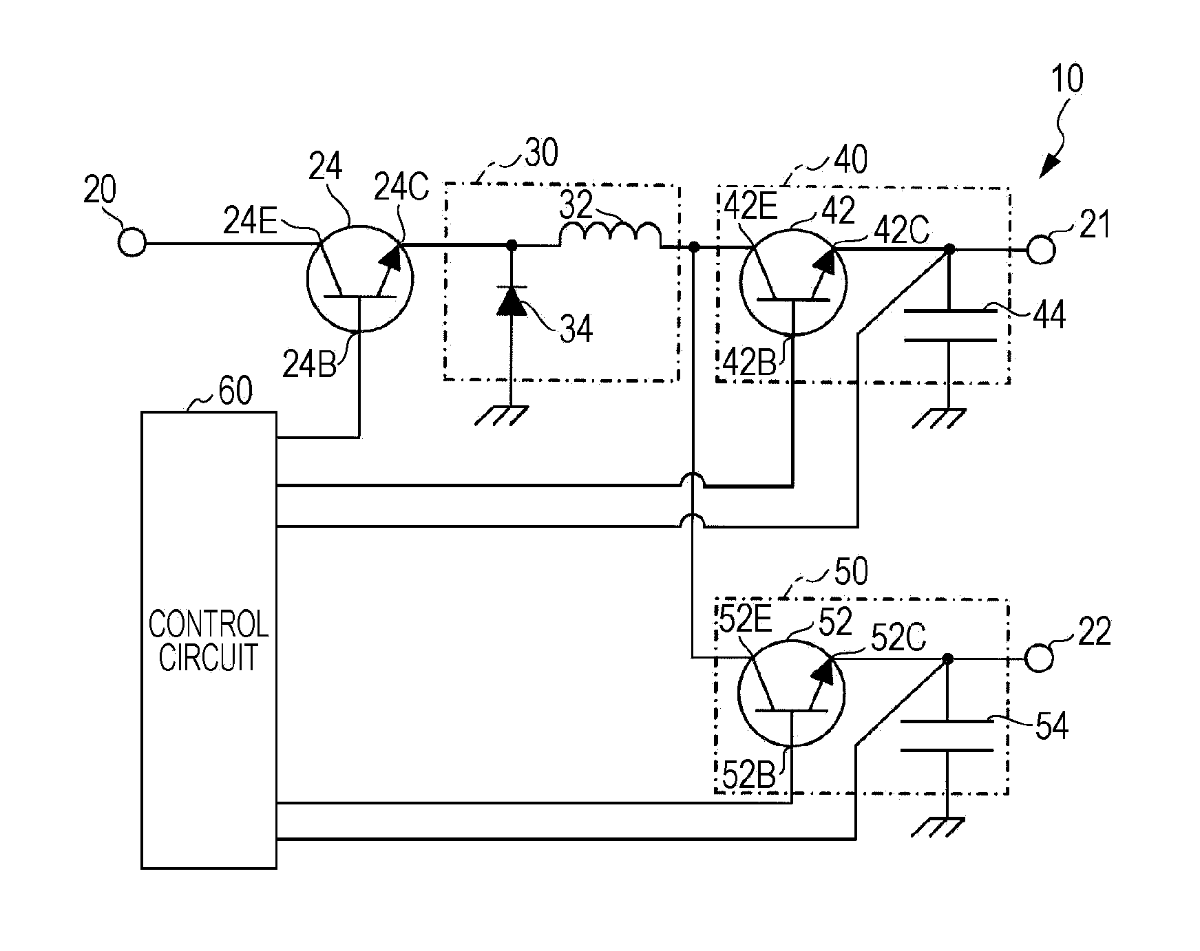
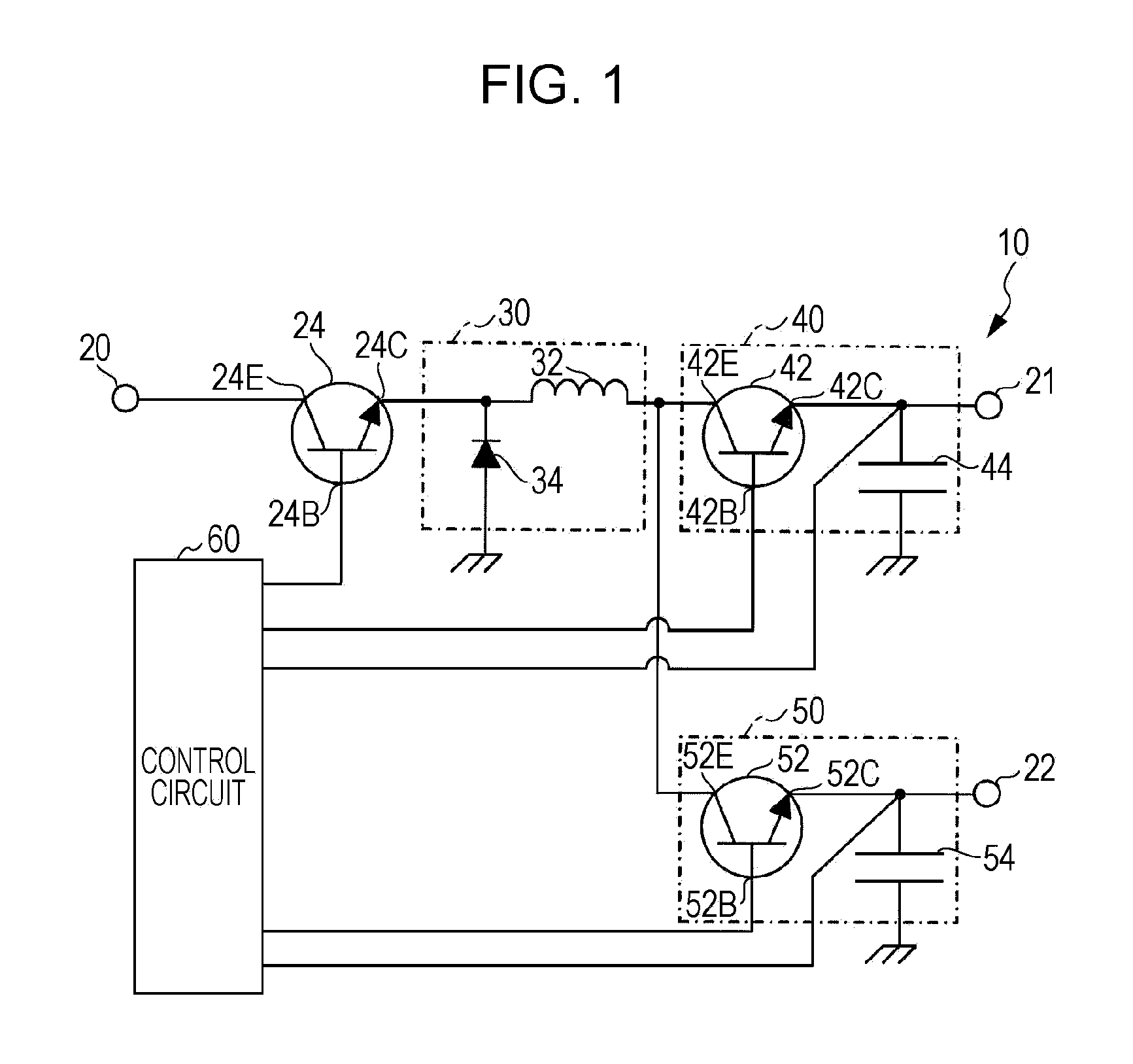
[0030]FIG. 1 is a configuration view illustrating a general configuration of a switching device 10 according to a first embodiment. The switching device 10 according to the first embodiment is configured as a DC-DC converter that receives the input of a DC voltage and outputs the DC voltage in the transformed form, in an electronic apparatus such as a multi-function device and a printer. To do this, the switching device 10 includes an input terminal 20, a first output terminal 21, a second output terminal 22, a main switching element 24, a rectification circuit 30, a first output circuit 40, a second output circuit 50, and a control circuit 60. Furthermore, the switching device 10 is configured as a step-down converter that enables each of the first and second output terminals 21 and 22 to output the voltage that is the result of stepping down a voltage from a DC power supply.

[0031]The input terminal 20 is connected to the DC power supply (not shown) outputting a given voltage (for ...

second embodiment

[0059]FIG. 5 is a configuration view illustrating a general configuration of a switching device 110 according to a second embodiment. Furthermore, in the switching device 110 according to the second embodiment, the same elements as those of the switching device 10 are given like reference numerals and are not described.

[0060]The switching device 110 according to the second embodiment includes an input terminal 20, first and second output terminals 21 and 22, a main switching element 124, a rectification circuit 130, first and second output circuits 40 and 50, and a control circuit 60. The switching device 110 is configured as a step-up converter that enables each of the first and second output terminals 21 and 22 to output the voltage that is the result of stepping down the voltage from the DC power supply.

[0061]The input terminal 20 is connected to a DC power supply (not shown) outputting a given voltage (for example, 20V). The input terminal 20 is a terminal which receives the inp...


PUM


Abstract

A switching device is disclosed in which electric current through a rectification circuit, depending on whether a main switching element turns on or off, and thus electric current from the rectification circuit flows through whichever of first and second sub-switching elements, turns on. By controlling the turning on and off of the first and second sub-switching elements, the switching is performed which determines through which of the first and second output circuits the electric current from the rectification circuit flows. Thus, a voltage that is a result of transforming a voltage from a DC power supply in response to the electric current flowing through the first output circuit, is output from a first output terminal, and a voltage that is a result of transforming a voltage from the DC power supply in response to the electric current flowing through the second output circuit, is output from a second output terminal.

Description

INCORPORATED BY REFERENCE [0001]The entire disclosure of Japanese Patent Application No. 2011-206801, filed Sep. 22, 2011 is expressly incorporated by reference herein.BACKGROUND[0002]1. Technical Field[0003]The present invention relates to a switching device and a method of controlling a switching device.[0004]2. Related Art[0005]A DC-DC converter, which receives the input of a voltage from a DC power supply and outputs the voltage in a transformed form, has been known as a switching device. For example, a DC-DC converter is described in JP-A-05-83939, which includes a transistor, as a switching element, and a rectification circuit including a diode and a coil. The DC-DC converter steps down the voltage input from the DC power supply and outputs the voltage in the transformed form. Furthermore, a DC-DC converter is described in JPA-2000-116127, which receives an input of one voltage from the DC power supply and outputs plural voltages through being connected in parallel to a rectif...

Claims


Application Information

Patent Timeline
IPC IPC(8): G05F1/46
CPCG05F1/46H02M3/158H02M1/009
Inventor SAKO, YASUHIKO
Owner SEIKO EPSON CORP
Why Eureka
Try Eureka