
Circuit breaker having an unlocking mechanism and methods of operating same

a technology of circuit breakers and unlocking mechanisms, which is applied in the direction of circuit breakers, circuit breakers for excess current, circuit breakers operating/releasing mechanisms, etc., and can solve problems such as the inability of circuit breakers to electrically protect one or more electrical branch circuits

Active Publication Date: 2013-04-11
SIEMENS IND INC
View PDF4 Cites 12 Cited by
  • Summary
  • Abstract
  • Description
  • Claims
  • Application Information

AI Technical Summary

Benefits of technology

This patent describes an electronic circuit breaker that includes a lockout mechanism. The lockout mechanism includes a lockout latch that has one or more pivot joints, a moveable stop, and an engagement portion. The engagement portion is offset from the pivot axis. The lockout latch is designed to normally block motion of the moveable contact arm, but when an unlock force is applied to the engagement portion, the lockout latch pivots and releases the moveable contact arm. The electronic circuit breaker may also have secondary electrical contacts that are engaged when the handle is moved between an ON and OFF configuration, and a leaf spring that flexes to close the secondary electrical contacts in the ON configuration. The invention also provides a method for operating the electronic circuit breaker by actuating the lockout latch with the unlock force to release the moveable contact arm to a closed configuration. Overall, the patent describes a mechanism that ensures safe and reliable operation of the electronic circuit breaker.

Problems solved by technology

If one or more of the electronic components in such a circuit breaker fails in some way, the circuit breaker may be unable to electrically protect the one or more electrical branch circuits that are connected to the circuit breaker.

Method used


Image

  • Circuit breaker having an unlocking mechanism and methods of operating same
  • Circuit breaker having an unlocking mechanism and methods of operating same
  • Circuit breaker having an unlocking mechanism and methods of operating same

Examples


Embodiment Construction

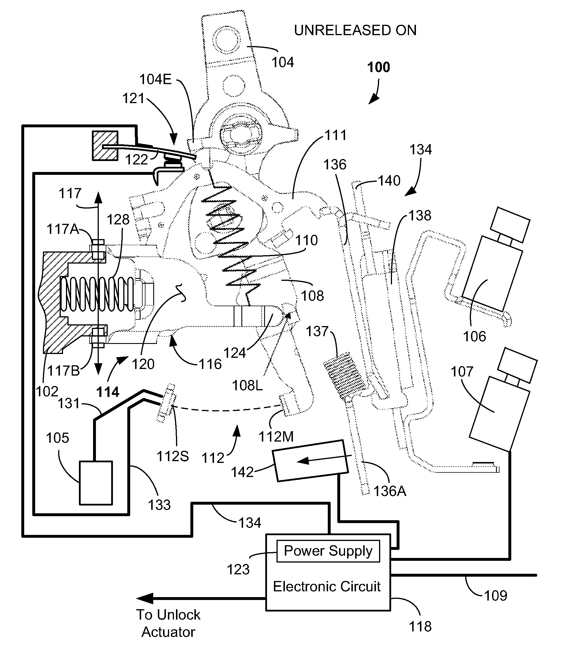
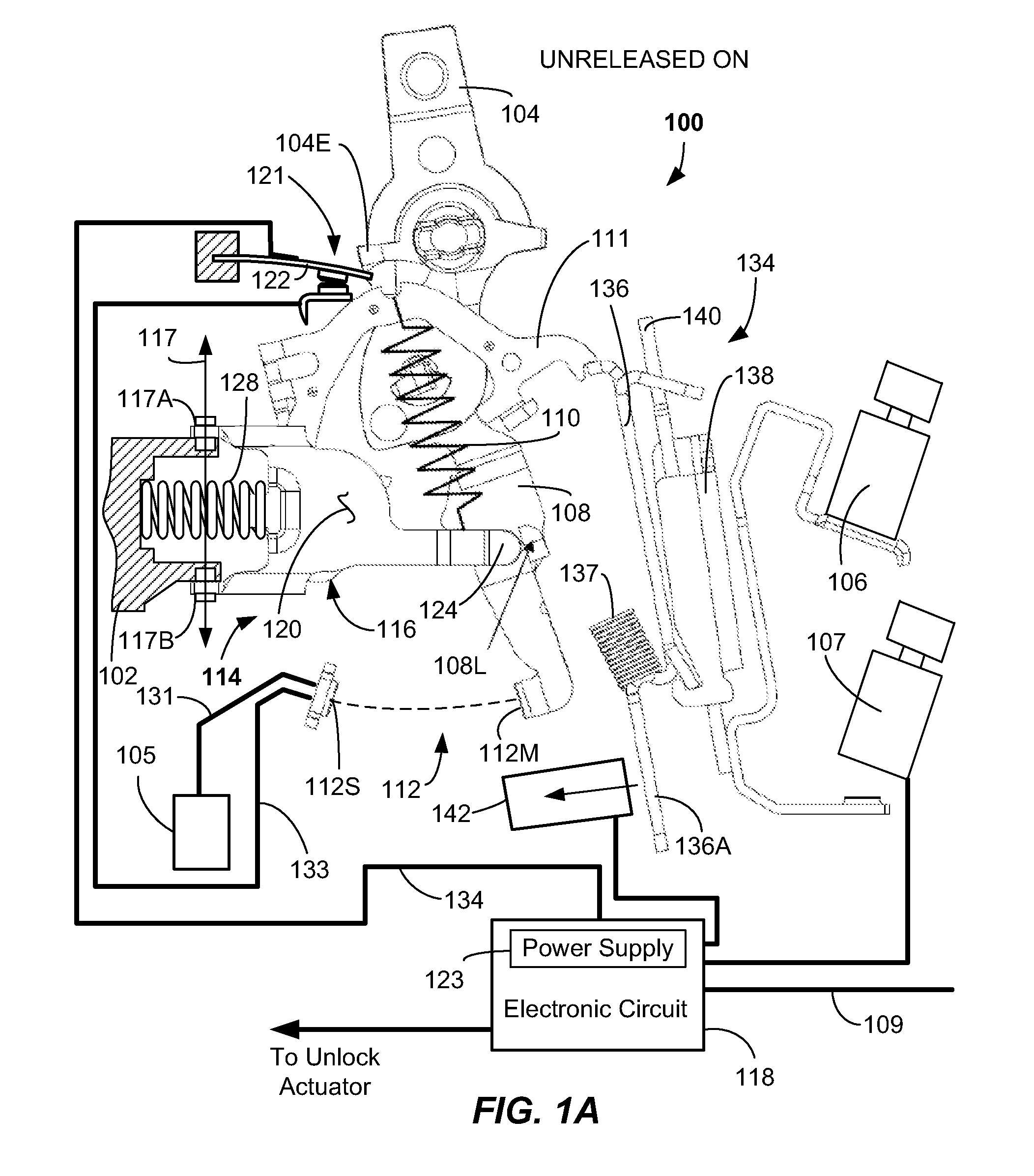
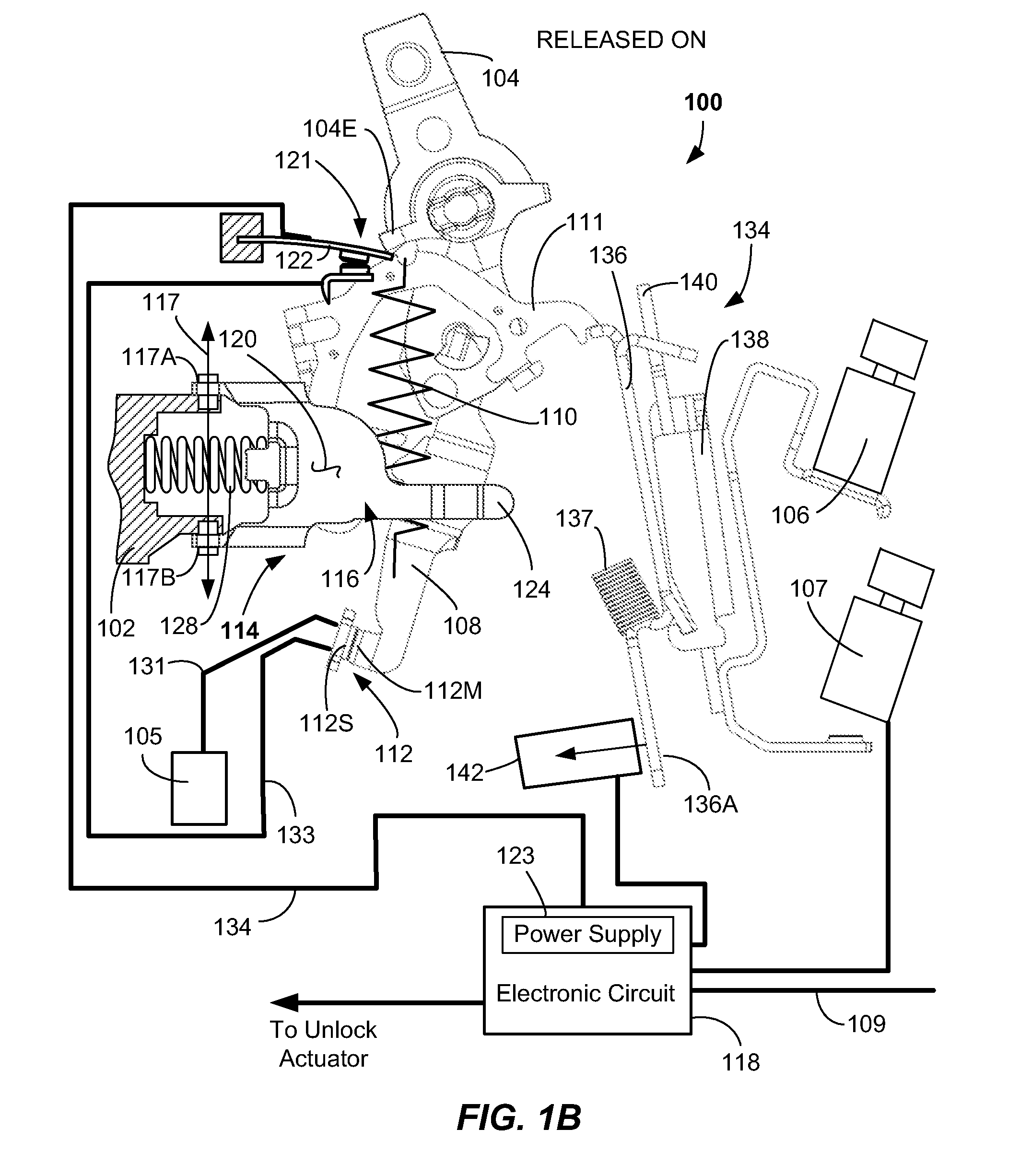
[0018]In view of the foregoing difficulties, a circuit breaker is provided that has a unlocking mechanism with a moveable stop adapted to allow locking and unlocking of a moveable contact arm of the circuit breaker. In particular, the unlocking mechanism is locked as the handle is moved toward an ON configuration. The electronic circuit breaker includes main electrical contacts and secondary electrical contacts. According to one aspect, closing of the secondary electrical contacts is accomplished in the ON configuration. Secondary electrical contact closing may be used to initiate powering of the internal electronic circuit of the circuit breaker. Once powered, a self test may be carried out on the internal electronic circuit of the circuit breaker in the locked state. If the self test is passed, then the moveable contact arm may be unlocked. through disengaging the moveable stop of the unlocking mechanism from the moveable contact arm. This allows the moveable contact arm to move s...


PUM


Abstract

Embodiments provide an electronic circuit breaker. The electronic circuit breaker has a moveable contact arm having a moveable main electrical contact, and a lockout mechanism operable to contact the moveable contact arm and block motion of thereof, the lockout mechanism having a lockout latch with one or more pivot joints, a moveable stop, and an offset engagement portion, the moveable stop adapted to contact the moveable contact arm, and an unlock actuator providing an unlock force at the engagement portion causing lockout latch pivoting and release of the moveable contact arm. Also disclosed are secondary electrical contacts configured to engage each other in the ON configuration, with a leaf spring operably supporting a moveable one of the secondary contacts, the leaf spring configured to be flexed to close the secondary contacts. A method of operating the electronic circuit breaker is provided, as are other aspects.

Description

FIELD OF THE INVENTION[0001]The present invention relates generally to a circuit breaker for interrupting current from an electrical power supply, and more particularly to a circuit breaker including an unlocking mechanism.BACKGROUND OF THE INVENTION[0002]Circuit breakers are used in certain electrical systems for protecting an electrical circuit coupled to an electrical power supply. For example, electronic circuit breakers, such as Arc Fault Circuit Breakers (AFCIs), Ground Fault. Circuit. Interrupters (GFCIs), Transient Voltage Surge Suppressors (TVSSs), and surge protectors, use electronic components to detect certain types of faults, such as arc faults and ground faults.[0003]If one or more of the electronic components in such a circuit breaker fails in some way, the circuit breaker may be unable to electrically protect the one or more electrical branch circuits that are connected to the circuit breaker. Accordingly, it would be desirable to check the electronic circuit or elec...

Claims


Application Information

Patent Timeline
IPC IPC(8): H01H77/06H01H9/20
CPCH01H9/20H01H77/06H01H71/62H01H71/505H01H71/46
Inventor YANG, GUANGBIEDRZYCKI, TIMOTHY
Owner SIEMENS IND INC
Learn More