Wrist case and wrist watch device

a wrist watch and wrist watch technology, applied in the field of wrist watches, can solve the problems of large distance between the respective ends of the wrist watches straps, uncomfortable wear of devices equipped with such large cases, and inability to wear, etc., to achieve optimal water tightness and aesthetic appearance, simple construction, and maximum usable space

Active Publication Date: 2013-04-11
SUUNTO OY
View PDF5 Cites 25 Cited by
  • Summary
  • Abstract
  • Description
  • Claims
  • Application Information

AI Technical Summary

Benefits of technology

[0006]It is thus the object of the present invention to overcome the above mentioned disadvantages. It is particularly an object to realize a watch case of rather large size allowing both integration of numerous electronic components required by the corresponding watch device and comfortable wear of the same by all persons irrespective of their wrist diameter. It is also an object to have a watch being of robust and relatively simple construction, leaving a maximum of usable space in its inside. It is also an object to have a watch assuring optimal water tightness and aesthetic appearance, as well as keeping its production cost comparatively low. Furthermore, it is the object of the present invention to realize corresponding watch straps to be used in connection with such a watch case as well as a corresponding wrist watch device incorporating such a watch case.

Problems solved by technology

These diverse functions requiring corresponding electronic components inside the watch, such wrist computers usually are quite voluminous and, in particular, often need to be equipped with watch cases of rather large size, some of these devices having in fact a width of 4 cm to 6 cm or even more.
In the mentioned case of large wrist computers this causes a large distance between the respective ends of the watch straps, i.e. between their axes of attachment to the watch case.
Consequently, devices equipped with such large cases are rather uncomfortable, if not impossible, to wear by persons having a small wrist diameter.
This aspect is even worse for a category of conventional wrist computers which have a case made up of a first part of appreciably circular shape which is prolonged in the direction of one of its watch straps by a second part of appreciably longitudinal shape and of similar width like the watch strap.
This means that the disadvantage in view of the wearing of such devices by persons having a small wrist is even more accentuated for such kind of devices, even though the watch case prolongation is usually inclined downwards in order to better fit the shape of a human wrist.
A second aspect caused by the large size of such devices lies in the body of the watch case itself.
In fact, watch cases for such devices may have quite complicated shapes, e.g. in the above mentioned case of watch cases made up of a first part of appreciably circular shape prolonged by a second, downwards bent part of appreciably longitudinal shape.
However, there are important disadvantages of such construction, especially due to the fact that the individual parts making up the watch case in most of the cases need to be assembled in water tight manner, given that most wrist computers are designed for applications requiring water tightness.
A main housing with a split design, of course, requires a gasket of quite complicated shape, which by definition may cause future problems in view of the water tightness of the device.
Also, the total surface to be sealed is increased, which not only diminishes reliability of water tightness but moreover is voluminous, thus further reducing the space available for the electronic components of the device.
Watch cases with a main body made up of several parts suffer drawbacks in this respect, because of evidently being less robust, since any bonding between parts is typically a weakness in construction, as well as being less easy to use by the end user.
At the same time, such boundary interfaces impose limits on the design of the device and are potentially negative for its aesthetic perception, since not allowing to have surfaces with a clean look all over the watch case.
Moreover, ensuring water tightness on 3D (not flat) interconnecting surfaces is more challenging, hence costly and subject to defects.
Prior art watch cases and wrist watch devices of the type described here above thus inherently comprise several problems and disadvantages.

Method used


Image

  • Wrist case and wrist watch device
  • Wrist case and wrist watch device
  • Wrist case and wrist watch device

Examples


Embodiment Construction

[0022]In the following, the invention shall be described in detail with reference to the above mentioned figures.

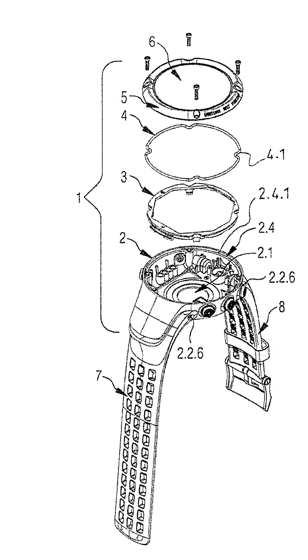
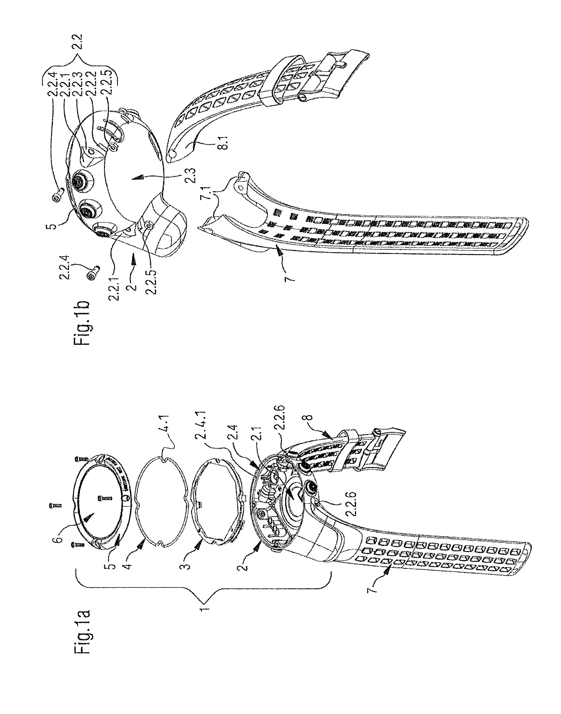
[0023]As can be seen in convenient manner in FIG. 1a which shows an exploded perspective top view on a wrist watch device comprising a watch case as well as watch straps according one preferred embodiment of the present invention, a watch case 1, such as proposed by the present invention is adapted to form part of a wrist watch device, like the type of wrist computers mentioned in the introduction. In particular, the watch case 1 according to the present invention comprises a main body 2 for the watch case, an annular securing ring 3 which is situated in the assembled state of the watch case at the upper end of the main body 2 near its opening 2.4 and allows to secure the other components of the device, like e.g. the watch movement, the energy source, et cetera, inside the main body 2, a gasket 4 also situated in the assembled state of the watch case at the level of the o...


PUM


Abstract

The present invention is related to a watch case adapted to be integrated into a wrist watch device, the watch case comprising an inner volume for housing internal components of the wrist watch device and attachment elements for attaching at least one watch strap of the wrist watch device, wherein at least one portion of the inner volume of the watch case extends laterally (or longitudinally) beyond the points of attachment of the at least one watch strap. The present invention is also directed to a corresponding watch strap as well as to a wrist watch device comprising such a watch case.

Description

RELATED APPLICATIONS[0001]The present application claims priority to European Patent Application Serial No. 11 008080.1 entitled WATCH CASE AND WRIST WATCH DEVICE, and filed on Oct. 5, 2011.FIELD OF THE INVENTION[0002]The present invention relates generally to a watch case adapted to be integrated into a wrist watch device, the watch case comprising an inner volume for housing internal components of the wrist watch device and attachment elements for attaching at least one watch strap of the wrist watch device, as well as to a corresponding watch strap respectively a corresponding wrist watch device.BACKGROUND OF THE INVENTION[0003]In general, the present invention relates to wrist watches and wrist-top computers, which may be equipped with numerous functions, including for example location determination, especially by means of the global positioning system (GPS), capture and analysis of the cardiac frequency of the user of the device, altimetric—and barometric applications, and the ...

Claims


Application Information

Patent Timeline
Patent Type & Authority Applications(United States)
IPC IPC(8): G04B37/14G04B47/06
CPCG04R60/10G04G17/08G04B37/1486G04B37/0058G04G21/04
Inventor PERKO, PANUMANNI, JUKKA
Owner SUUNTO OY
Why Eureka
Try Eureka