Flexibly bended boot for optical fiber connector

a technology of optical fiber connectors and boots, which is applied in the manufacture of contact parts, instruments, optical elements, etc., can solve the problems of difficult angled connectors, power loss of optical signals passing through optical fibers, and complicated moving parts

Inactive Publication Date: 2013-04-18
PROTAI PHOTONIC +1
View PDF5 Cites 101 Cited by
  • Summary
  • Abstract
  • Description
  • Claims
  • Application Information

AI Technical Summary

Problems solved by technology

An optical signal passing through an optical fiber can experience a power loss if the bend radius of the optical fiber is too great.
However, the connector ...

Method used


Image

  • Flexibly bended boot for optical fiber connector
  • Flexibly bended boot for optical fiber connector
  • Flexibly bended boot for optical fiber connector

Examples


Embodiment Construction

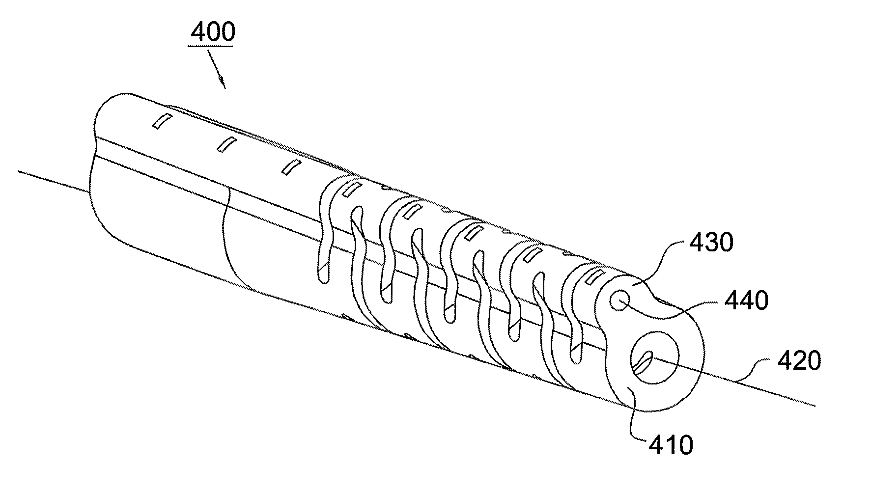
[0022]Referring to FIGS. 4 and 5, the flexibly bended boot 400 of the present invention is for an optical fiber connector. The boot 400 is adjacent to an optical fiber connector and surrounds an optical fiber (not shown in the figures). The boot 400 includes an elastic hollow body 410 which is cylindrical and defines an axial direction 420. A protrusion portion 430 is integrally formed on the outer surface of the body 410 along the axial direction 420. In addition, a member 440 with the property of plasticity is axially embedded in the protrusion portion 430. The member 440 can be integrally formed and is a metal wire, such as an iron wire

[0023]According to the present invention, the boot 400 can be bent to a desired shape in subjection to an external force. When the boot 400 is bent, the member 440 will also be bent accordingly. Since the member 440 has the property of plasticity, the boot 400 can still be kept in the desired shape even though when the external force vanishes. Simi...


PUM

PropertyMeasurementUnit
Plasticityaaaaaaaaaa

Abstract

A boot for an optical fiber connector according to the present invention is provided. The boot includes a hollow cylindrical body defining an axial direction, a protrusion portion formed on the cylindrical body, and a member with the property of plasticity disposed in the protrusion portion, wherein the member has at least one protrusion formed thereon The at least one protrusion sticks in the protrusion portion formed on the cylindrical body.

Description

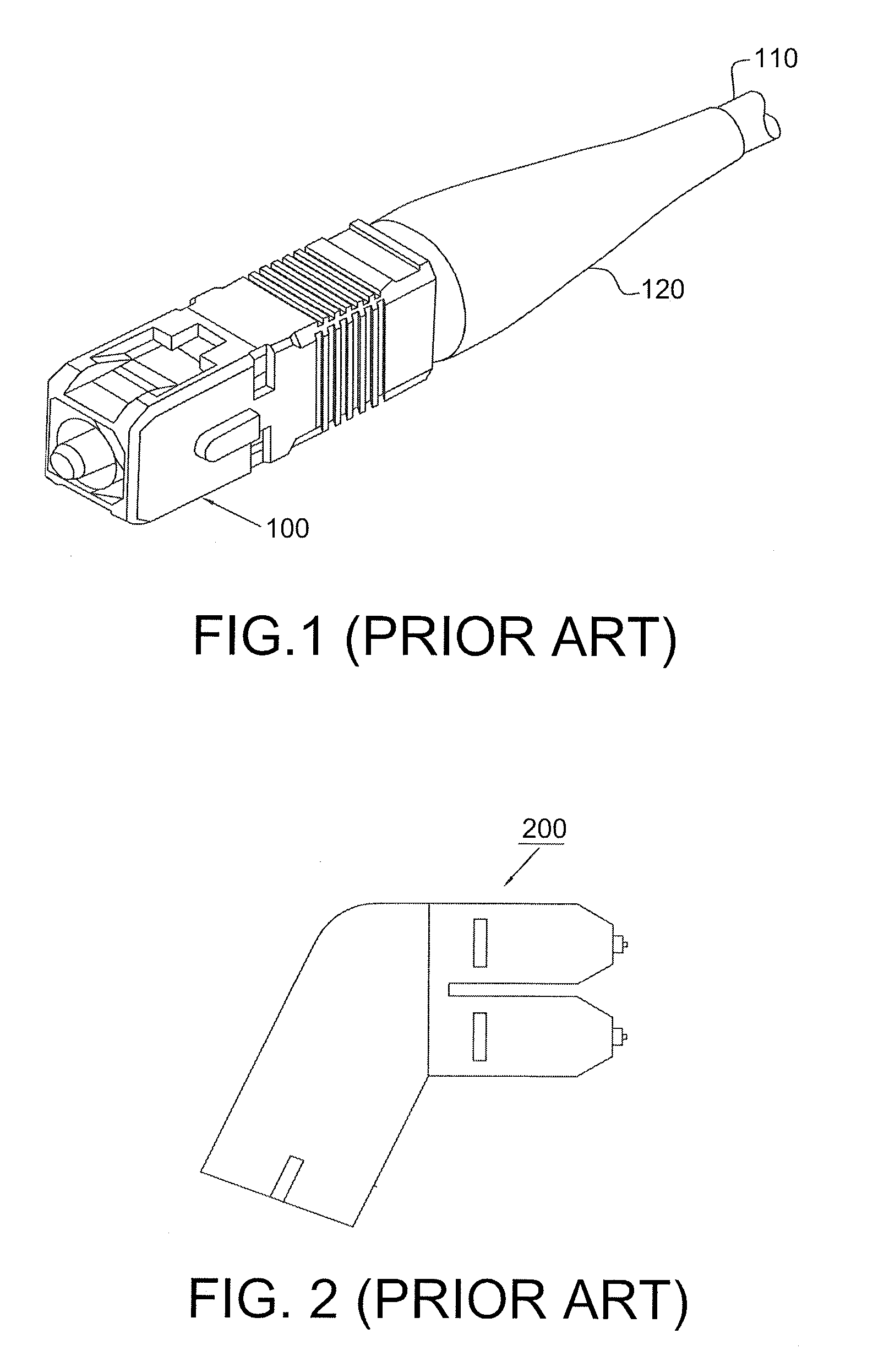
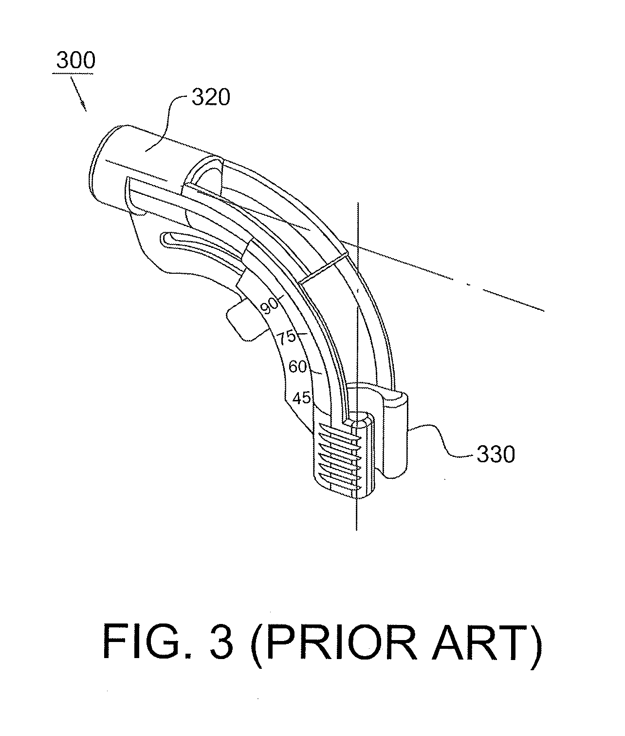
BACKGROUND OF THE INVENTION[0001]1. Field of the Invention[0002]The invention relates to an optical fiber connector, and more particularly, to a boot for an optical fiber connector.[0003]2. Description of the Related Art[0004]The application of fiber optics to the telecommunication and data storage industries is expanding ever day. Fiber optics enables the high-speed transmission of communications and data. Connectors for optical fibers can be found in the back of instrumentation, telecommunication, routing, and switching cabinets. These cabinets accept a large number of fiber optical connectors. The optical fibers project away from the connector and tend to bend toward the ground due to the effect of gravity or the optical fibers are bent in a different direction due to an externally applied force. An optical signal passing through an optical fiber can experience a power loss if the bend radius of the optical fiber is too great. In order to prevent the optical fiber from being bent...

Claims


Application Information

Patent Timeline
IPC IPC(8): G02B6/36H01R43/00
CPCY10T29/49204G02B6/3887G02B6/38875
Inventor LIN, I ENMAMIYA, TOMOYUKIGNIADEK, JEFFERY
Owner PROTAI PHOTONIC
Why Eureka
Try Eureka