Power management in an eye-tracking system

a power management and eye tracking technology, applied in the field of eye tracking, can solve the problems of not addressing the power management problem in the eye detection equipment itself, not addressing the power management in the eye tracker itself, and affecting an otherwise optimized energy management, so as to improve power management, improve power management, and improve power management. the effect of functionalities

Active Publication Date: 2013-05-02
TOBII TECH AB
View PDF12 Cites 73 Cited by
  • Summary
  • Abstract
  • Description
  • Claims
  • Application Information

AI Technical Summary

Benefits of technology

[0007]In view of the above concerns, it is an object of the present invention to propose a personal computer system with improved power management functionalities in respect of eye-tracking equipment included therein. It is a particular object to improve power management in a system of this type while preserving low latency in respect of user interactions at all instants when the device is operating. Yet another object is to provide an eye-tracking system that can be integrated in a personal computer system (e.g., desktop or laptop computer, tablet computer, notebook, net book, TV, smart phone, personal digital assistant, digital camera, heads-up display, near-eye display) without burdening the energy performance of the computer system.

Problems solved by technology

In the case of battery-powered systems, concerns that eye-tracking functionalities might impair an otherwise optimized energy management may be one reason for this absence.
While this document describes how an eye detection result, namely eye presence, can be used to improve the energy performance of the generic device, it does not address the power management problem in the eye detection equipment itself.
Nor does it propose any solution that is tailored to, and benefits from, the particularities associated with eye detection activity.
They also do not address power management in the eye tracker itself.

Method used


Image

  • Power management in an eye-tracking system
  • Power management in an eye-tracking system
  • Power management in an eye-tracking system

Examples


Embodiment Construction

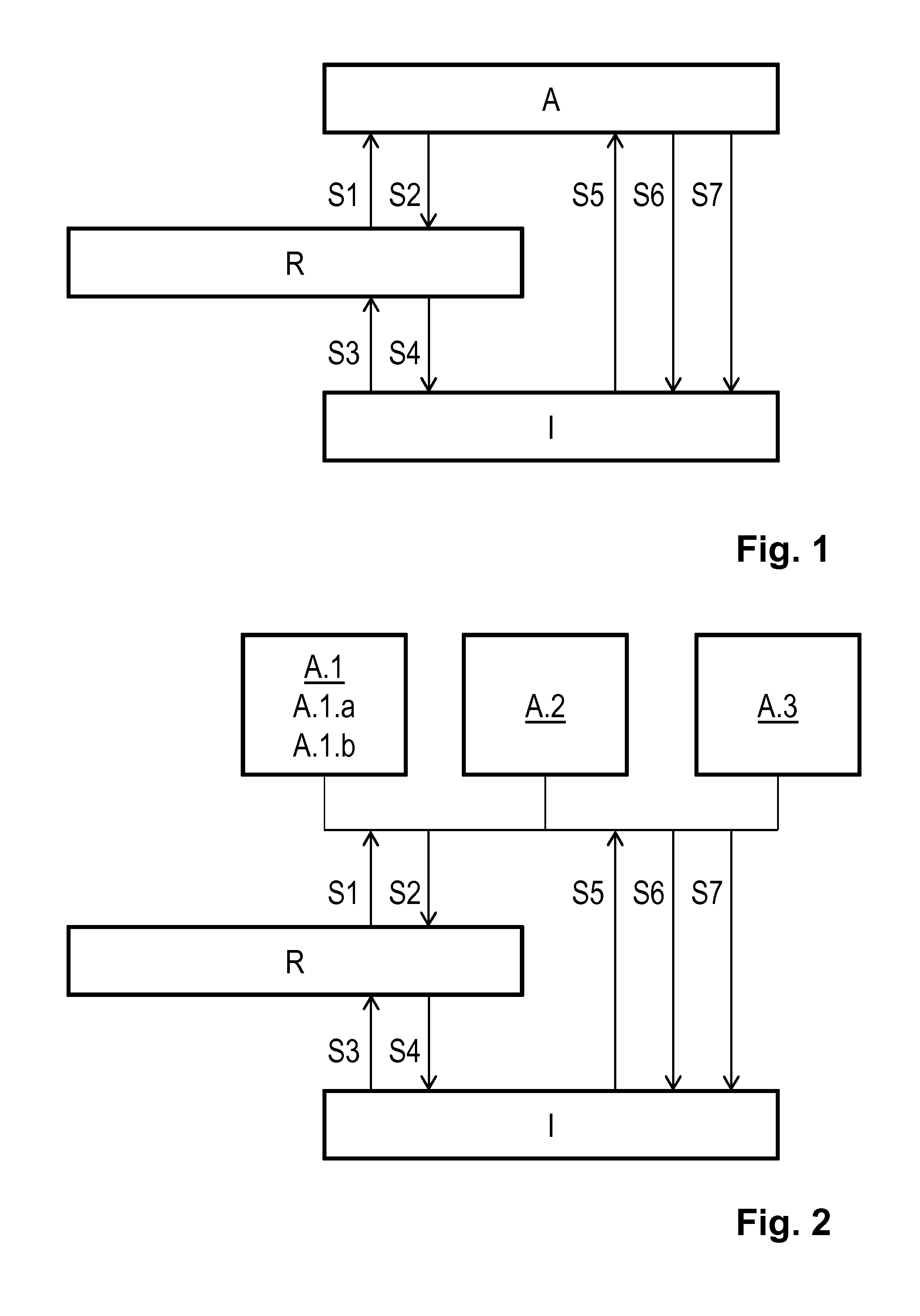
[0036]FIG. 1 schematically shows an active mode A, a ready mode R and an idle mode I of a imaging device in an eye tracker. As outlined above, the eye tracker performs computations of a recursive nature or uses historic data, so that, on the one hand, a given computing or measuring task may be facilitated or expedited by results or intermediate results from previous computations and measurements and, on the other hand, the eye tracker has considerable wake-up time before it provides accurate and complete output data. No result history is maintained in the idle mode, whereas a full result history—allowing the eye tracker to take full advantage of the previous computations and measurements—is maintained in the active mode. The full result history may refer to a moving time window of values, whereby the least recent values are discarded as new ones are entered. The ready mode is characterized by producing and maintaining a partial result history (e.g., lower sample rate, fewer samples ...


PUM


Abstract

A personal computer system includes a visual display, an imaging device adapted to provide eye-tracking data by imaging the face of a viewer of the visual display, and an input device for accepting eye-tracking control data and other input data. The imaging device is switchable between at least an active mode, a ready mode and an idle mode, and the switching time from the idle mode to the active mode is longer than the switching time from the ready mode to the active mode. The eye-tracking data provided in the ready mode may include eye position but not eye orientation. The system may include a dedicated input device for forcing the imaging device into active mode by directly triggering an interrupt; alternatively, the dedicated input device forces it permanently into idle mode.

Description

TECHNICAL FIELD OF THE INVENTION[0001]The invention disclosed herein generally relates to eye tracking (determination of eye position, gaze point or gaze angle) for providing input data to a computer system. In particular, the invention provides an energy-efficient implementation of eye tracking assisted by an artificial light source adapted to determine the gaze point of an eye watching a visual display forming part of a portable or stationary personal computer system, a TV, a heads-up display in a vehicle, a near-eye display or a display in a communication device with imaging and computing capabilities, such as a mobile telephone.BACKGROUND OF THE INVENTION[0002]Monitoring or tracking eye movements and detecting a person's gaze point can be used in many different contexts. Eye tracking data can be an important information source in analyzing the behavior or consciousness of the person. It can be used both for evaluating the object at which the person is looking and for evaluating ...

Claims


Application Information

Patent Timeline
Patent Type & Authority Applications(United States)
IPC IPC(8): G09G5/00
CPCG06F3/013G09G2354/00G09G2330/021G06V40/18H04N23/667G02B27/0172G02B2027/0138
Inventor ESKILSSON, HENRIKSKOGÖ, MÅRTENELVESJÖ, JOHNBLIXT, PETER
Owner TOBII TECH AB
Why Eureka
Try Eureka