Intelligent user mode selection in an eye-tracking system

a user mode and eye tracking technology, applied in the field of eye tracking, can solve the problems of not addressing the power management problem in the eye detection equipment itself, not addressing the power management in the eye tracking itself, and the eye tracking functionalities might impair an otherwise optimized energy management, so as to improve power management, improve power management, and improve the effect of power managemen

Active Publication Date: 2014-10-23
TOBII TECH AB
View PDF1 Cites 32 Cited by
  • Summary
  • Abstract
  • Description
  • Claims
  • Application Information

AI Technical Summary

Benefits of technology

[0009]In view of the above concerns, it is an object of the present invention to propose a personal computer system with improved power management functionalities in respect of eye-tracking equipment included therein. It is a particular object to improve power management in a system of this type while preserving low latency in respect of user interactions at all instants when the device is operating. Yet another object is to provide an eye-tracking system that can be integrated in a personal computer system (e.g., desktop or laptop computer, tablet computer, notebook, net book, TV, smart phone, personal digital assistant, digital camera, heads-up display, near-eye display) without burdening the energy performance of the computer system. A further object is to facilitate the use of one eye-tracking enabled personal computer system by many users. In such a system, it is a particular desire to simplify and accelerate the transitions between different viewers and / or decrease the risk of human errors in connection with the transitions.

Problems solved by technology

In the case of battery-powered systems, concerns that eye-tracking functionalities might impair an otherwise optimized energy management may be one reason for this absence.
While this document describes how an eye detection result, namely eye presence, can be used to improve the energy performance of the generic device, it does not address the power management problem in the eye detection equipment itself.
Nor does it propose any solution that is tailored to, and benefits from, the particularities associated with eye detection activity.
They also do not address power management in the eye tracker itself.
A further possible reason that eye-tracking functionalities are not yet included as standard components in personal computer systems is the hassle that may arise in connection with transitions between different users.

Method used


Image

  • Intelligent user mode selection in an eye-tracking system
  • Intelligent user mode selection in an eye-tracking system
  • Intelligent user mode selection in an eye-tracking system

Examples


embodiment 13

[0102]a negative detection signal causing the imaging device to switch from ready mode into idle mode.[0103]14. The personal computer system of embodiment 13, wherein:

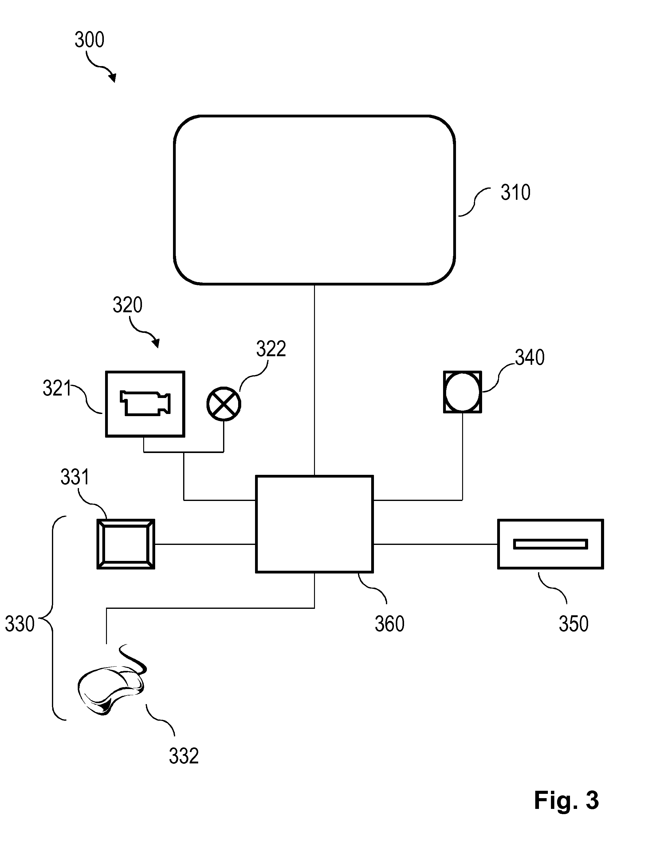
[0104]the viewer presence detector (340) is a proximity sensor at a push button and is arranged to sense proximity of a finger; and

[0105]the proximity sensor is configured to provide a positive detection signal causing the image device to switch from idle mode into ready mode.[0106]15. The personal computer system of any of the preceding embodiments, wherein the imaging device is configured to use active eye illumination in the active mode and the ready mode, the illumination intensity in the ready mode being less than the illumination intensity in the active mode.[0107]16. A method in a personal computer system comprising:

[0108]a visual display;

[0109]an imaging device comprising one or more cameras and being adapted to provide eye-tracking data by imaging at least one eye of a viewer of the visual display; and

[0110]in...

embodiment 16

[0111]said method comprising switching the imaging device between at least an active mode, a ready mode and an idle mode, wherein the switching time from the idle mode to the active mode is longer than the switching time from the ready mode to the active mode.[0112]17. A computer program product comprising a data carrier storing instructions for causing a programmable computer to execute the method of


PUM


Abstract

A personal computer system comprises a visual display, an imaging device adapted to provide eye-tracking data by imaging at least one eye of a viewer of the visual display, and identifying means for recognizing the viewer with reference to one of a plurality of predefined personal profiles. The personal computer system further comprises an eye-tracking processor for processing the eye-tracking data. According to the invention, the eye-tracking processor is selectively operable in one of a plurality of personalized active sub-modes associated with said personal profiles. The sub-modes may differ with regard to eye-tracking related or power-management related settings. Further, the identifying means may sense an identified viewer's actual viewing condition (e.g., use of viewing aids or wearing of garments), wherein the imaging device is further operable in a sub profile mode associated with the determined actual viewing condition.

Description

TECHNICAL FIELD OF THE INVENTION[0001]The invention disclosed herein generally relates to eye tracking (determination of eye position, gaze point or gaze angle) for providing input data to a computer system. In particular, the invention provides an energy-efficient implementation of eye tracking assisted by an artificial light source adapted to determine the gaze point of an eye watching a visual display forming part of a portable or stationary personal computer system, a TV, a heads-up display in a vehicle, a near-eye display or a display in a communication device with imaging and computing capabilities, such as a mobile telephone.BACKGROUND OF THE INVENTION[0002]Monitoring or tracking eye movements and detecting a person's gaze point can be used in many different contexts. Eye tracking data can be an important information source in analysing the behaviour or consciousness of the person. It can be used both for evaluating the object at which the person is looking and for evaluating...

Claims


Application Information

Patent Timeline
Patent Type & Authority Applications(United States)
IPC IPC(8): G06F1/32G06K9/00G06F3/01
CPCG06F1/3231G06K9/00221G06F1/3265G06F3/013G06F1/3287Y02D10/00G06V40/16
Inventor ELVESJO, JOHN MIKAELKINGBACK, ANDERSTROILI, GUNNARSKOGO, MARTENESKILSSON, HENRIKBLIXT, PETER
Owner TOBII TECH AB
Why Eureka
Try Eureka