Device and Method for Generating Vacuum for Vacuum Cementing Systems

Active Publication Date: 2013-05-09
HERAEUS MEDICAL
View PDF22 Cites 4 Cited by
  • Summary
  • Abstract
  • Description
  • Claims
  • Application Information

AI Technical Summary

Benefits of technology

[0006]It is an object of the invention to overcome the disadvantages of the prior art. In particular, a mobile and lightweight device for generating vacuum for cementing systems is to be provided. It would also be advantageous if the device did not require long and heavy hoses and did not need to be connected to stationary

Problems solved by technology

This procedure is disadvantageous in that air inclusions may be present in the cement dough thus formed and cause destabilization of the bone cement later on.
These hose systems are heavy and always associated with a risk of accidents since they are routed on the floor.
Since long hoses are used in thi

Method used


Image

  • Device and Method for Generating Vacuum for Vacuum Cementing Systems
  • Device and Method for Generating Vacuum for Vacuum Cementing Systems
  • Device and Method for Generating Vacuum for Vacuum Cementing Systems

Examples


Embodiment Construction

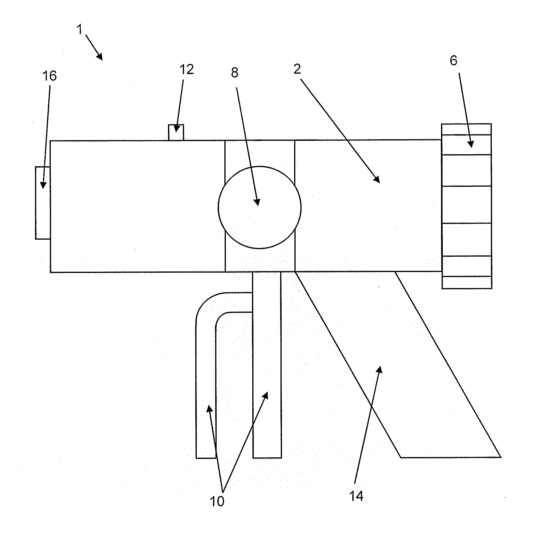
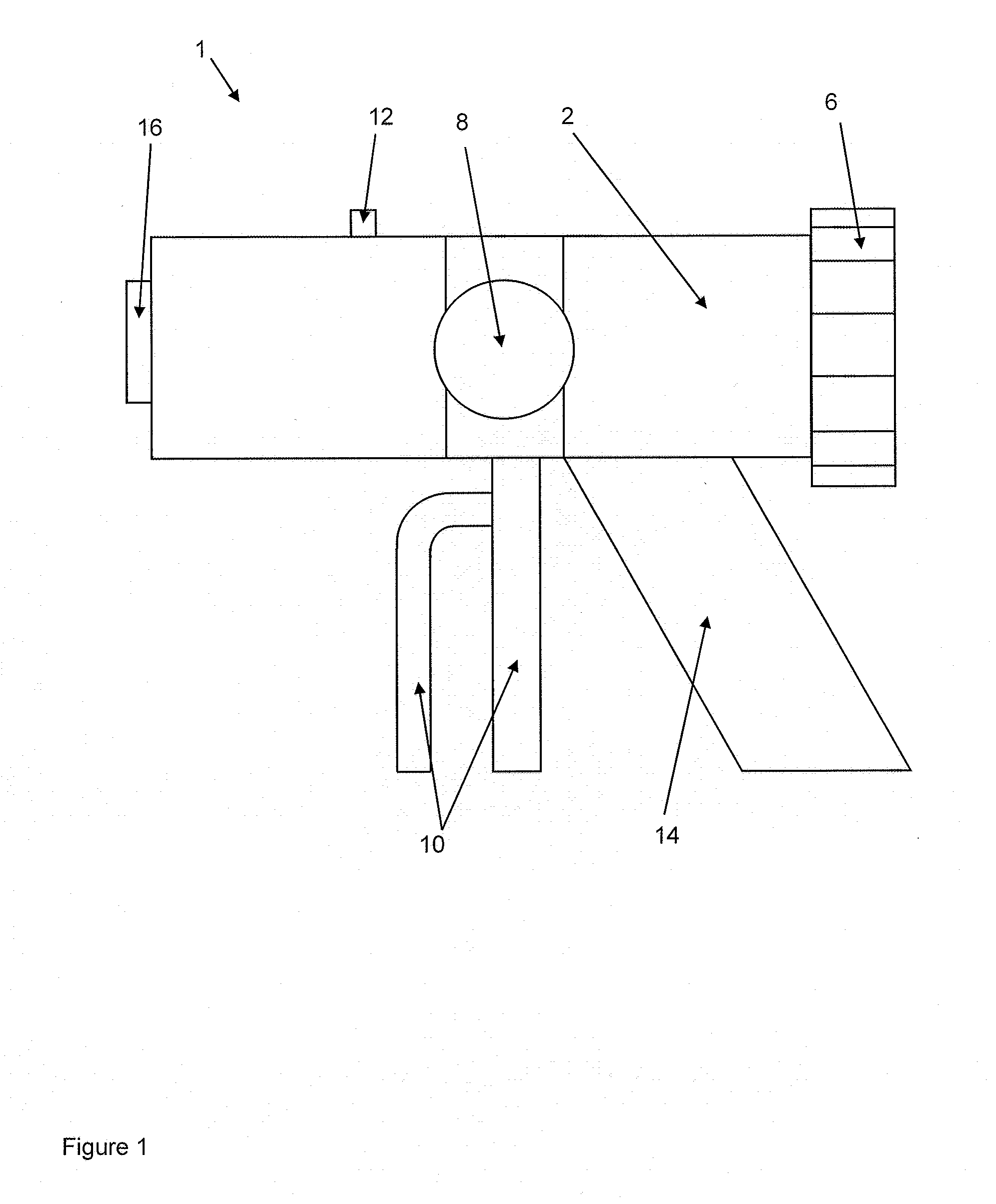
[0081]FIG. 1 shows a schematic cross-sectional view of a device 1 according to an embodiment of the invention for generating a vacuum for a vacuum cementing device. The device 1 comprises a housing 2 having a gas cartridge (not shown) arranged in it. The rear side of the device 1 is closed by a screw lid 6, such that the gas cartridge can be shifted on the inside of the device and pressed onto a mandrel or blade that opens the gas cartridge.

[0082]A rotatable valve 8 is arranged in the middle of the device 1 and can be used to open and close a channel (not shown) arranged on the inside of the device 1. The rotatable valve 8 is conical in shape and comprises a bushing that can connect a front part and a rear part of the channel in suitable position of the valve 8 and thus opens the channel. The rotatable valve 8 is shaped slightly conical and is seated in a press-fit in an opening of the housing 2 in the device 1, such that a gas-tight connection of the bushing to the channel or gas-t...


PUM


Abstract

A device is provided for generating a vacuum for a vacuum cementing device, the device including a channel and a connector for a gas cartridge. The connector has an opener for opening the gas cartridge, and connects the gas cartridge to the channel in a pressure-tight manner, such that gas from the opened gas cartridge flows along the channel to the surroundings of the device. The channel includes at least one T-piece, provided as Venturi nozzle, having a vacuum connector for the vacuum cementing device, such that gas from the opened gas cartridge flowing through the channel generates a negative pressure at the vacuum connector. A method is also provided including steps of opening a gas cartridge, flowing gas from the gas cartridge through a Venturi nozzle, whereby by a negative pressure is generated, and applying the negative pressure to a vacuum cementing system.

Description

BACKGROUND OF THE INVENTION[0001]The invention relates to a device for generating a vacuum for a vacuum cementing device. The invention also relates to a method for generating a negative pressure in a vacuum cementing system.[0002]Conventional PMMA bone cements have been known for decades and are based on the ground-breaking work of Sir Charnley (Charnley, J., “Anchorage of the Femoral Head Prosthesis of the Shaft of the Femur,”J. Bone Joint Surg. 42: 28-30 (1960)). The basic structure of PMMA bone cements has remained the same ever since. PMMA bone cements consist of a liquid monomer component and a powder component. The monomer component generally contains the monomer, methylmethacrylate, and an activator (N,N-dimethyl-p-toluidine) dissolved therein. The powder component consists of one or more polymers made by polymerization, preferably suspension polymerization, based on methylmethacrylate and co-monomers, such as styrene, methylacrylate or similar monomers, a radio-opacifier, a...

Claims


Application Information

Patent Timeline
IPC IPC(8): F04F5/14
CPCA61B17/8822A61B17/8825A61B17/8827A61B2017/883F04F5/20B01F2215/0029B01F13/0027B01F33/50114B01F2101/20
Inventor WUST, EDGARVOGT, SEBASTIAN
Owner HERAEUS MEDICAL
Why Eureka
Try Eureka