Electric servo press machine

a servo press and electric technology, applied in the direction of presses, press rams, manufacturing tools, etc., can solve the problems of difficult the need to stop the sliding immediately, and a certain length of time to stop the moving body, so as to achieve the effect of smooth recovery of operation and simple and cost-efficient configuration

Inactive Publication Date: 2013-05-16
AIDA ENG LTD
View PDF3 Cites 1 Cited by
  • Summary
  • Abstract
  • Description
  • Claims
  • Application Information

AI Technical Summary

Benefits of technology

[0019]According to the present invention, it is possible to provide the electric servo press machine which drives the slide via the power transmission path using the electric servomotor in a relatively simple and cost-efficient configuration. The electric servo press machine includes the clutch mechanism and the brake mechanism provided in the power transmission path, and at the time of, for example, immediate stop, the electric servomotor is disconnected from the power transmission path by the clutch mechanism, and the brake mechanism is actuated to stop the slide. In this electric servo press machine, when the electric servomotor is connected to the power transmission path again by the clutch mechanism, the phase shift between the electric servomotor side and the slide side can be eliminated, thereby smoothly recovering the operation to the normal operation.

Problems solved by technology

However, when stopping the slide due to abnormality in the servo such as a servo error and a positional error, or when stopping the slide by issuing an emergency stop signal from an emergency stop device due to button operation performed by a person or detection of intrusion into a dangerous area, the slide needs to be stopped immediately.
At this time, as the inertia of the moving body to be stopped becomes larger, it becomes more difficult to stop the moving body, and hence a certain length of time is required to stop the moving body.
Therefore, the electric servo press machine is increased in size and cost.
However, when the electric servomotor and the crankshaft (slide) are decoupled from each other by the clutch mechanism as described above, the phases of the electric servomotor and the crankshaft are shifted from each other (synchronization therebetween is not achieved).
Therefore, when the clutch mechanism is directly connected for the recovery to the normal operation, troubles may occur in the press working after the recovery and further in cooperative working with other apparatus and facilities in a press working line, which is not a stand-alone system but is a system configured in cooperation with other apparatus and facilities.

Method used


Image

  • Electric servo press machine
  • Electric servo press machine
  • Electric servo press machine

Examples


first embodiment

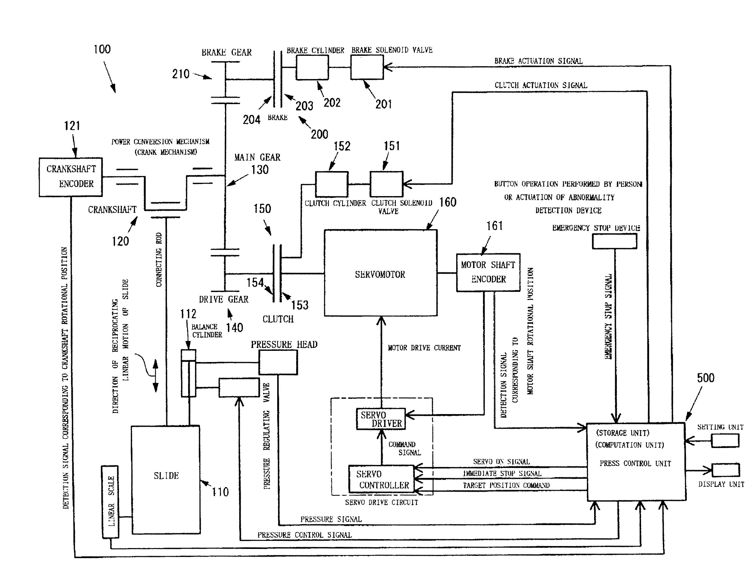
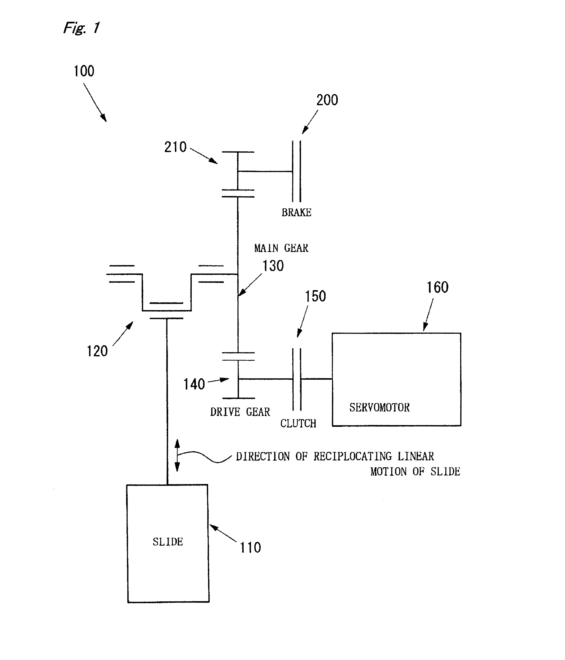
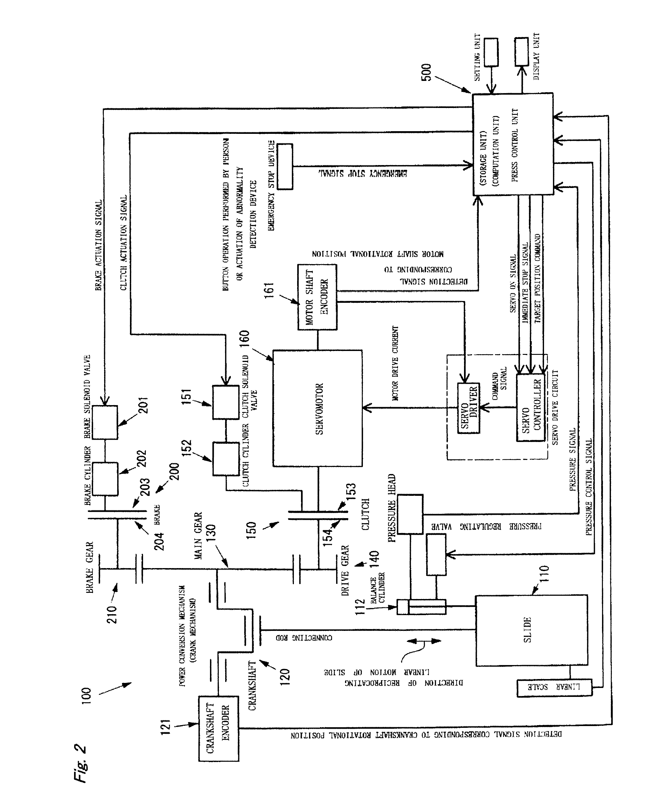
[0029]As illustrated in FIGS. 1 and 2, an electric servo press machine 100 according to a first embodiment of the present invention includes a crank mechanism (which may be constructed as a mechanism utilizing an eccentric shaft or the like) including a crankshaft 120 as one of “rotary-to-reciprocating linear motion conversion mechanisms” for linearly reciprocating a slide 110 which performs press working on a workpiece.

[0030]A main gear 130 is integrally mounted on the crankshaft 120, and a drive gear 140 and a brake gear 210 mesh with the main gear 130.

[0031]An electric servomotor 160 as a drive source of the electric servo press machine 100 according to the present invention is rotationally coupled to a rotation shaft of the drive gear 140, and a clutch mechanism 150 is interposed between the drive gear 140 and the electric servomotor 160.

[0032]As the clutch mechanism 150, an electromagnetic clutch mechanism or other various types of clutch mechanism may be employed. For example,...

second embodiment

[0070]A second embodiment of the present invention is different from the first embodiment only in the method of recovery to the normal operation after the immediate stop, and hence only this matter is described below.

[0071]That is, as the recovery method of the second embodiment, for example, the following method is employed. That is, as illustrated in Steps 108 to 111 (S108 to S111) in a control flow chart of FIG. 4A, the press control unit 500 which controls the electric servomotor 160 drives the electric servomotor 160 to rotate the electric servomotor 160 relative to the crankshaft 120 (rotating body located in the power transmission path ranging from the clutch mechanism 150 in the disconnected state to the slide 110) until the rotational angle position information of the electric servomotor 160, which is acquired based on the information from the motor shaft encoder 161 of the electric servomotor 160, matches with the rotational angle position information of the crankshaft 120...

third embodiment

[0085]A third embodiment of the present invention is an example in which the present invention is applied to an electric servo press machine 600 as illustrated in FIG. 5 other than the electric servo press machine 100 of the first and second embodiments illustrated in FIGS. 1 and 2.

[0086]Although the basic concept is the same as those in the first and second embodiments, the electric servo press machine 600 is different in layout from the electric servo press machine 100 of FIG. 1, and an intermediate gear 300 is interposed between the clutch mechanism 150 and the electric servomotor 160. With this configuration, there is an advantage in that a speed reduction ratio and the like can be set to desired values as compared to the first and second embodiments, that is, the degree of freedom in design is increased. In other respects, the configuration and control of the third embodiment are similar to those of the above-mentioned first and second embodiments, and a similar action and effe...


PUM


Abstract

An electric servo press machine is configured to convert a rotation of an electric servomotor into a reciprocating linear motion of a slide to perform press working on a workpiece. The machine includes a clutch mechanism interposed in a power transmission path between the servomotor and the slide, and a brake mechanism for applying a brake onto the slide under a disconnected state in which the servomotor and the power transmission path are decoupled from each other by the clutch mechanism. The machine brings the clutch mechanism into the disconnected state and applies the brake onto the slide upon an immediate stop request, and recovers from immediate stop under a state in which a phase shift between the servomotor and the power transmission path ranging from the clutch mechanism in the disconnected state to the slide is eliminated under a connected state of the clutch mechanism.

Description

FIELD OF THE INVENTION[0001]The present invention relates to an electric servo press machine which converts a rotation of a servomotor into a vertical reciprocating motion of a slide through an intermediation of a power transmission / conversion mechanism, and utilizes the vertical reciprocating motion of the slide to perform press working on a workpiece.BACKGROUND[0002]There is known a pressing machine (so-called electric servo press machine (pressing machine); the press machine (pressing machine) may be hereinafter referred to simply as “press”) which converts a rotation of an electric servomotor under electronic control into a vertical reciprocating motion of a slide through an intermediation of a power transmission / conversion mechanism (for example, a crank mechanism), and utilizes the vertical reciprocating motion of the slide to perform press working on a workpiece.[0003]A growing number of electric servo presses have been employed due to their advantages in that an operation st...

Claims


Application Information

Patent Timeline
Patent Type & Authority Applications(United States)
IPC IPC(8): B30B15/14
CPCB30B15/142B30B1/266B30B15/148
Inventor KOSHIMIZU, TAKASHI
Owner AIDA ENG LTD
Why Eureka
Try Eureka