Method and Device for Laser Inscribing

a laser and substrate technology, applied in laser beam welding apparatus, printing, manufacturing tools, etc., can solve the problem of large overall dimensions of laser inscribing

Inactive Publication Date: 2012-05-31
NANOSEC GES FUR NANOTECH & DER SICHERHEITSTECHN
View PDF7 Cites 2 Cited by
  • Summary
  • Abstract
  • Description
  • Claims
  • Application Information

AI Technical Summary

Benefits of technology

[0010]Thus it is the object of the invention to provide a method and device for laser inscribing cards which has small dimensions in spite of simple and cost efficient configuration and still facilitates fast inscribing.Solution
[0013]The reason is that through the deflection of the laser beam in only one direction the laser beam instead of having to be spread into a three dimensional cone only has to be spread into a two dimensional fan. Therefore the respective deflection mirror only has to have a significant extension in one direction, namely the width of the fan and can be configured very narrow in the other spatial direction. This is one of the reasons why the device can be configured overall smaller and more compact.
[0017]Since the moveable galvanometer mirror or polygon mirror, subsequently designated as fan mirror which deflects the laser beam in the space of a fan, is moved in increments according to the Y-positions of the pixels to be inscribed on the card, a control is required which controls the laser according to the angular position of the fan mirror and additionally also according to a current X-position of the card slide or the optical slide, thus causes a laser impact at the desired X-Y position and thus also controls the power of the laser.
[0027]Thus, the device becomes particularly simple in its configuration in that the laser beam is not deflected behind the selection mirror through the fixated deflection mirrors on each side of the main plane only by two deflection mirrors which are theoretically possible, but deflected through three deflection mirrors, wherein each of them provides a deflection by ninety degrees.
[0028]On the other hand side deflection mirrors with a reflection angle of this type can be purchased off the shelf and very economically, on the other hand side this has the effect at all deflection mirrors on each of the sides for double sided inscribing or six deflection mirrors are identical mirrors, thus due to identical reflection conditions have the same dielectric coating, namely a beam deflection of ninety degrees which would not be the case when using only two deflection mirrors on each side.

Problems solved by technology

This, however, causes rather large overall dimensions of the laser inscribing device

Method used


Image

  • Method and Device for Laser Inscribing
  • Method and Device for Laser Inscribing
  • Method and Device for Laser Inscribing

Examples


embodiments

[0039]Embodiments of the invention are subsequently described in more detail in drawing figures, wherein:

[0040]FIG. 1 illustrates block diagrams of the beam path;

[0041]FIG. 2: illustrates a device according to the invention in various views; and

[0042]FIG. 3: illustrates sectional views of the device of FIG. 2.

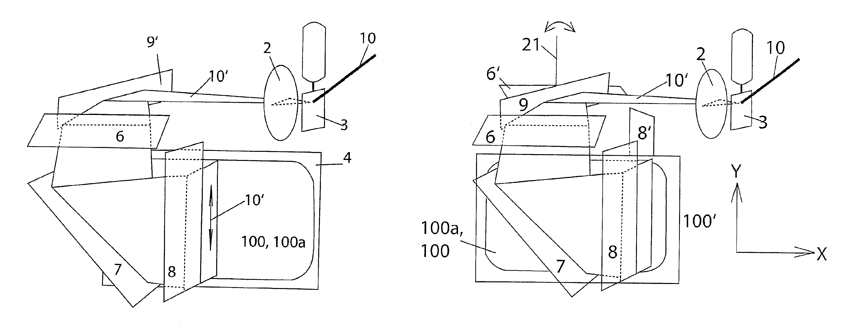
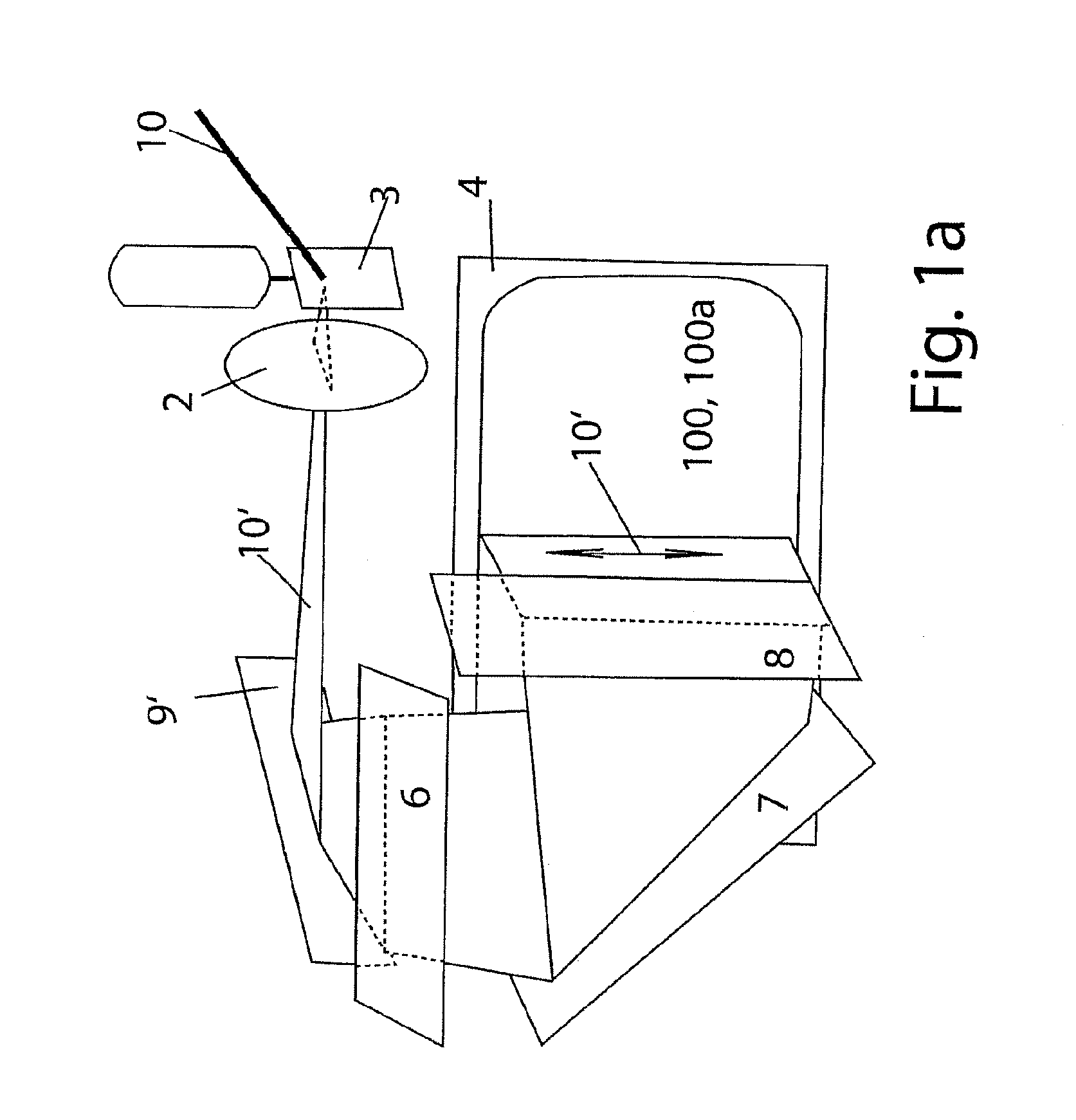
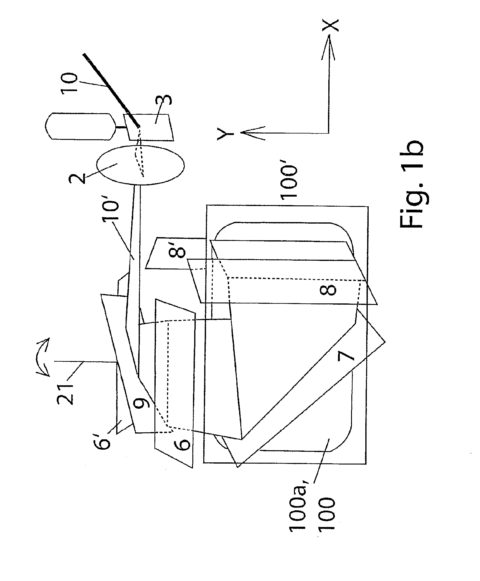
[0043]FIG. 1a illustrates the rectangular card 100 that shall be inscribed and which has the typical rounded corners and which is received in a form locking manner in a card slide 4 which is moveable in a controlled manner in x-direction, in this case the larger direction of the main plane of the card 100, and thus of the card slide 4.

[0044]A laser beam 10 is initially fanned into a beam fan 10′ adjacent to the card slide 4 through a fan mirror 3 pivoting back and forth by a defined angular amount in an oscillating motion, wherein the fan mirror 3 is respectively stopped in an intermediary portion in increments at defined angular positions according to the different Y-positions...


PUM

PropertyMeasurementUnit
pivot angleaaaaaaaaaa
movementaaaaaaaaaa

Abstract

In order to obtain a laser inscribing unit that is compact for inscribing cards on two sides which also includes a magnet chip inscribing unit, a laser beam is only deflected in one spatial direction in a fan shape, and in the other spatial direction the movement of the card received in the card slide is provided. In spite of inscribing the card in the same receiving position from the top side and also from the bottom side this yields a very compact configuration.

Description

FIELD OF THE INVENTION[0001]The invention relates to laser inscribing of card type substrates, e.g. ID cards, credit cards, check cards or similar flat, planar objects with two main surfaces extending parallel to one another wherein at least one of the surfaces is to be inscribed.BACKGROUND OF THE INVENTION[0002]Inscribing cards, in particular made from plastic material, through a laser is known in the art since the energy of the laser beam causes a carbonization and thus blackening of the carbon of the substrate and thus a permanent coloration with a depth effect in the base material.[0003]The coloration can be provided through absorption of the laser light through the substrate or portion of the substrate like e.g. embedded colorants etc. and through cracking encapsulating pigments open.[0004]Depending on the energy of the laser light and the positioning of the focal point, the inscribing effect can be provided at the surface or also in the depth of the substrate, wherein the latt...

Claims


Application Information

Patent Timeline
Patent Type & Authority Applications(United States)
IPC IPC(8): B23K26/00
CPCB41J2/471B41J2/442
Inventor KREUTER, RUDIGERKOSCHINSKI, WILLI
Owner NANOSEC GES FUR NANOTECH & DER SICHERHEITSTECHN
Why Eureka
Try Eureka