Transmission type radiation generating source and radiography apparatus including same

a radiation generating source and radiation technology, applied in the direction of x-ray tubes, material analysis using wave/particle radiation, instruments, etc., can solve the problems of unnecessary portion of radiation transmitted through and emitted from the substrate, and achieve the effect of satisfying heat dissipation performan

Inactive Publication Date: 2013-05-23
CANON KK
View PDF6 Cites 9 Cited by
  • Summary
  • Abstract
  • Description
  • Claims
  • Application Information

AI Technical Summary

Benefits of technology

[0009]The various embodiments of present invention are generally directed to a transmission type radiation generating device and a radiography apparatus including the same that reali

Problems solved by technology

Therefore, an unnecessary portion of the radiation trans

Method used


Image

  • Transmission type radiation generating source and radiography apparatus including same
  • Transmission type radiation generating source and radiography apparatus including same
  • Transmission type radiation generating source and radiography apparatus including same

Examples


first embodiment

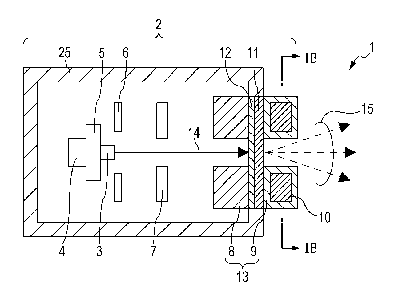
[0023]An electron emitting source 3 emits electrons in the form of an electron beam 14. The electron emitting source 3 may include, as a cathode, either a cold cathode or a hot cathode. If an impregnated cathode (a hot cathode) is applied to the electron emitting source 3 of the radiation generating device 1, a high current can be stably extracted even if the degree of vacuum is relatively high. The electron emitting source 3 is integrated with an insulating member 5 in the

[0024]A heater 4 is provided near the cathode. When energized, the heater 4 raises the temperature of the cathode and causes the cathode to emit electrons.

[0025]A grid electrode 6 is an electrode to which a predetermined voltage is applied so as to extract electrons generated from the cathode, i.e., the electron emitting source 3, into the vacuum and is provided at a predetermined distance from the electron emitting source 3. The shape, opening size, opening ratio, and so forth of the grid electrode 6, which is pr...

fifth embodiment

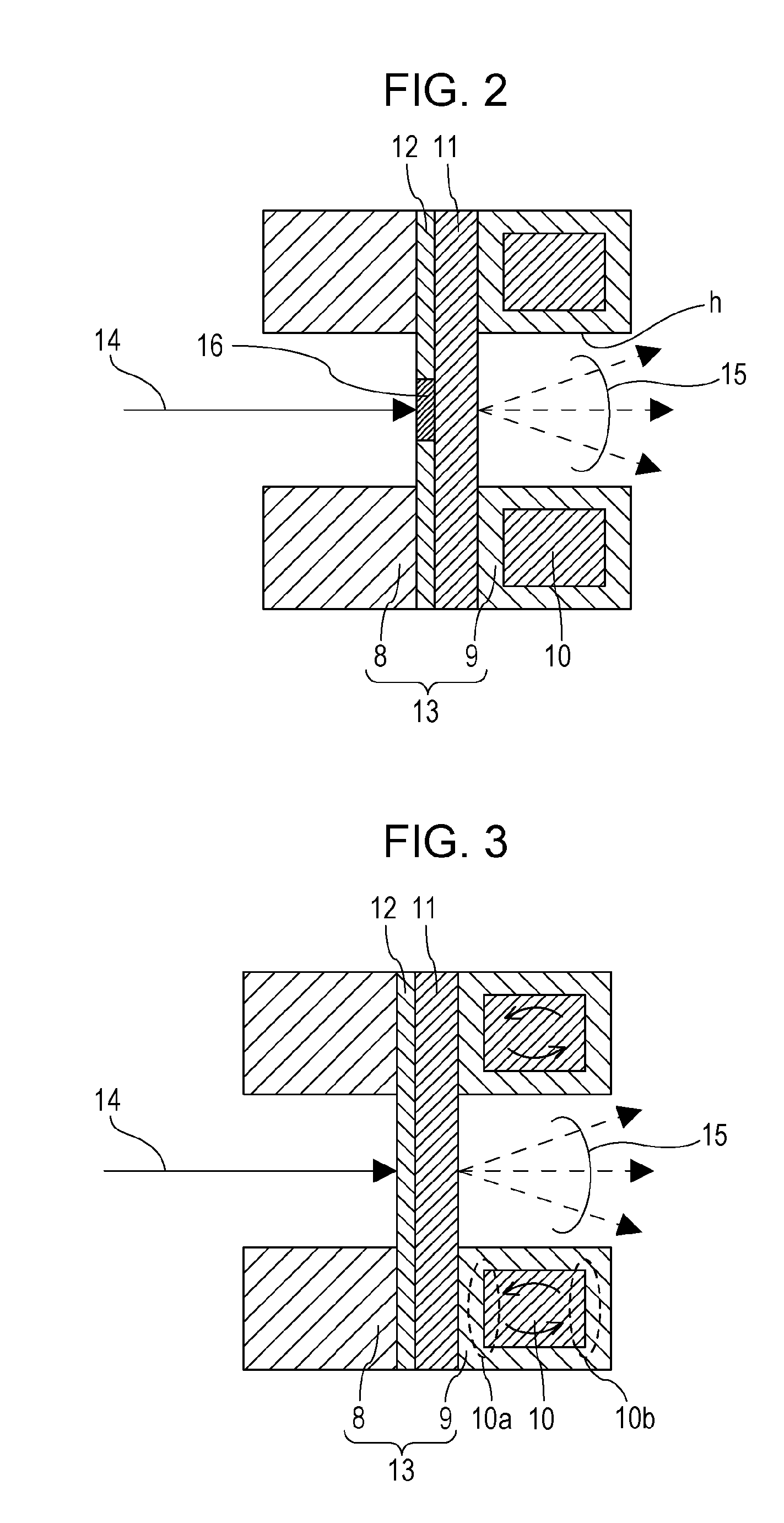
[0046]In the multiple radiation generating device including a plurality of radiation generating regions, the low-melting-point metal or alloy 10 included in the shield member 17 continuously extends over adjacent ones of the plurality of radiation generating regions. The present invention also encompasses an embodiment in which separate regions each including the low-melting-point metal or alloy 10 are allocated to the respective radiation generating regions that are adjacent to each other.

[0047]In the embodiment in which the low-melting-point metal or alloy 10 continuously extends over adjacent ones of a plurality of radiation generating regions, even if there are variations in the heat generation from the plurality of targets 12, such variations tend to become uniform over the entirety. Such a configuration is suitable for a case in which scanning is performed by using a plurality of electron emitting sources 3. In the embodiment in which separate regions each including the low-m...


PUM


Abstract

A transmission type radiation generating device includes an electron emitting source; a substrate that transmits radiation; a target provided on a surface of the substrate facing the electron emitting source and configured to generate radiation when electrons emitted from the electron emitting source are applied thereto; a shield member having a radiation passage that allows the radiation transmitted through the substrate to pass therethrough, the shield member being connected to the substrate and including at least a forward shield portion that protrudes in a direction away from the electron emitting source with respect to the target; and an insulating fluid in contact with the forward shield portion. The shield member includes a low-melting-point metal or a low-melting point alloy provided at least in the forward shield portion.

Description

BACKGROUND OF THE INVENTION[0001]1. Field of the Invention[0002]The present invention relates to a transmission type radiation generating device and a radiography apparatus including that device. These devices may be applicable to diagnosis in the field of medical devices, nondestructive X-ray photography in the field of industrial devices, and the like.[0003]2. Description of the Related Art[0004]In a radiation generating device used as a radiation source, electrons emitted from an electron emitting source are made to impinge upon a target made of metal having a high atomic number, such as tungsten, whereby radiation is generated. The radiation generated from the target is emitted in all directions. Therefore, a portion of the radiation unnecessary for imaging is blocked by providing one or more shield members made of radiation-blocking material, such as lead. This increases the size and weight of the radiation generating device. Japanese Patent Application Laid-Open No. 2007-26598...

Claims


Application Information

Patent Timeline
IPC IPC(8): H01J5/18G01N23/04
CPCH01J5/18G01N23/04H01J2235/087H01J2235/068H01J35/12H01J35/116
Inventor OGURA, TAKAOAOKI, SHUJITAMURA, MIKIUEDA, KAZUYUKIYANAGISAWA, YOSHIHIROSATO, YASUENOMURA, ICHIROYAMAZAKI, KOJI
Owner CANON KK
Why Eureka
Try Eureka