Eureka AIR delivers breakthrough ideas for toughest innovation challenges, trusted by R&D personnel around the world.

Heat dissipation device

a heat dissipation device and heat dissipation device technology, which is applied in the direction of insulated conductors, semiconductor/solid-state device details, instruments, etc., can solve the problems of difficult backflow of working fluid in heat pipes, adversely affecting normal operation of graphics cards, and limited heat dissipation efficiency of heat dissipation devices, etc., to achieve efficient heat dissipation of electronic devices

Inactive Publication Date: 2006-03-28
HON HAI PRECISION IND CO LTD
View PDF6 Cites 71 Cited by
  • Summary
  • Abstract
  • Description
  • Claims
  • Application Information

AI Technical Summary

Benefits of technology

[0006]Accordingly, an object of the present invention is to provide a heat dissipation device which comprises heat sinks and heat pipes readily mounted to the heat sinks.
[0007]Another object of the present invention is to provide a heat dissipation device which can efficiently dissipate heat from electronic devices mounted on add-on cards.

Problems solved by technology

These electronic components, especially GPU, on such cards often have extremely large computing power and, as a consequence, generate substantial heat that if not efficiently dissipated will adversely affect normal operation of the graphics cards.
It is then difficult for working fluid in the heat pipe to return back to the evaporative section from the condensative section.
Therefore, heat dissipation efficiency of the heat dissipation device is limited.

Method used


Image

  • Heat dissipation device
  • Heat dissipation device
  • Heat dissipation device

Examples


Embodiment Construction

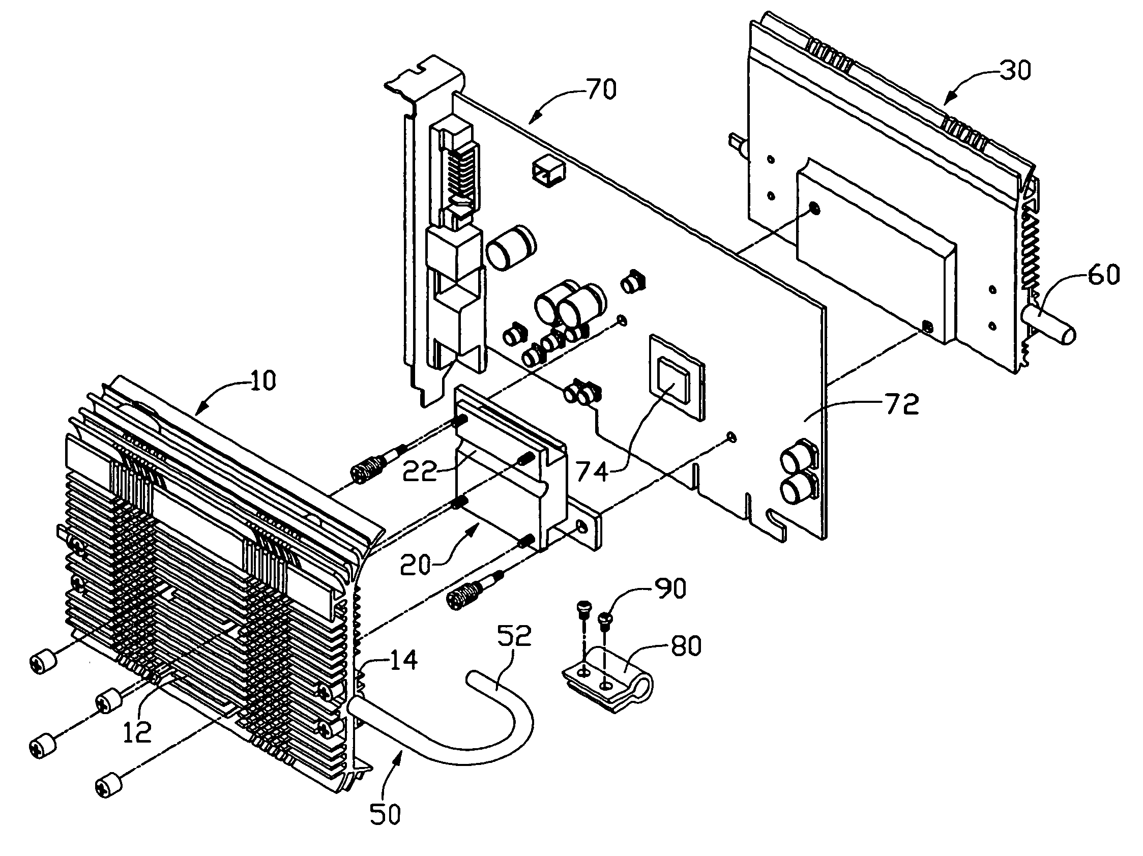
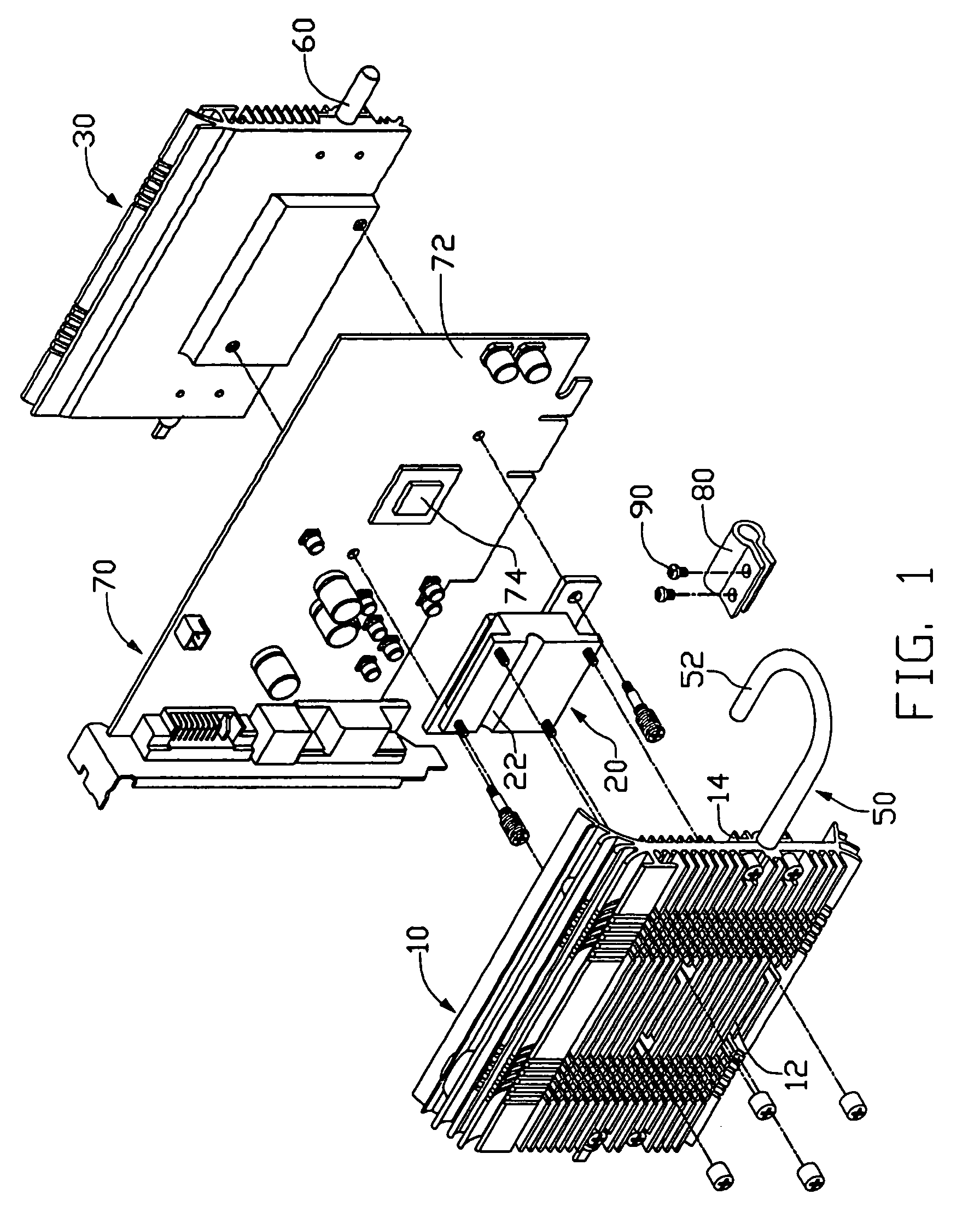
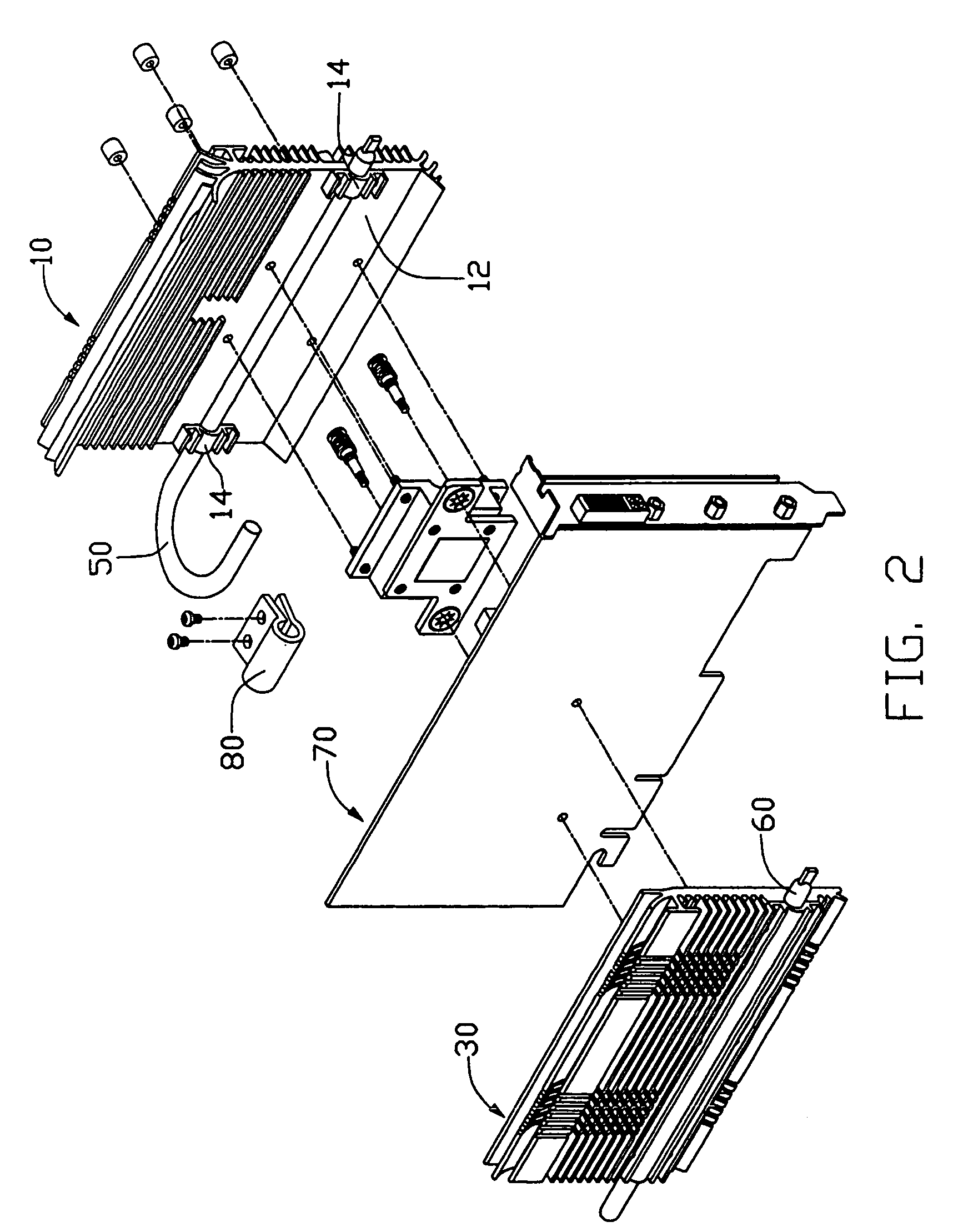
[0016]Referring to the attached drawings, FIGS. 1–2 show a heat dissipation device of in accordance with the first preferred embodiment of the present invention and an add-on card like a video graphic array (VGA) card 70. The heat dissipation device comprises a first heat dissipation unit, a second heat dissipation unit, a first heat pipe 50, a second heat pipe 60, and a connecting member 80. The VGA card 70 comprises a circuit board 72 on one side of which a graphic processing unit (GPU) 74 is mounted.

[0017]The first heat dissipation unit comprises a first heat sink 10 and a block 20. The first heat sink 10 comprises a plurality of heat dissipation fins 12. The block 20 is attached on one side of the first heat sink 10 by screws (not labeled). A longitudinal slot 22 is defined in one surface of the block 20 facing the first heat sink 10. The first heat pipe 50 is fixedly attached to the first heat sink 10 via two clips 14, extending through the slot 22 of the block 20. The first he...


PUM


Abstract

A heat dissipation device includes a first heat sink (10) mounted on one side of a video graphics adapter (VGA) card (70) on which a heat generating componnent (74) is mounted to dissipate heat generated by the heat generating componnent, a second heat sink (30) mounted on an opposite side of the card, a first heat pipe (50, 50′) thermally connected to the first heat sink, a second heat pipe (60, 60′) discrete from the first heat pipe thermally connected to the second heat sink, and a connecting member (80, 80′) connected between the first and second heat pipes for transferring heat from the first heat pipe to the second heat pipe.

Description

TECHNICAL FIELD[0001]The present invention relates to a heat dissipation device for electronic devices, and particularly to a heat dissipation device for an add-on card apparatus like a graphics card apparatus.BACKGROUND[0002]In order to enable desktop and other computers to rapidly and directly perform newly developed technology, like high-resolution graphics function, wireless communcation etc., add-on units including “graphics cards” or “video graphic array (VGA) cards” are often installed in computer devices to permit these computer devices enhancing their operative abilities. Using graphics cards as an example, such cards include a separate processor, called a graphic processing unit (GPU), one or more memory chips and other required circuitry, all mounted to a circuit board. These electronic components, especially GPU, on such cards often have extremely large computing power and, as a consequence, generate substantial heat that if not efficiently dissipated will adversely affe...

Claims


Application Information

Patent Timeline
Patent Type & Authority Patents(United States)
IPC IPC(8): H05K7/20
CPCG06F1/20H01L23/427H01L2924/0002H01L2924/00
Inventor LEE, HSIEH-KUNPENG, XUE-WENCHEN, RUI-HUA
Owner HON HAI PRECISION IND CO LTD
Why Eureka
Eureka Blog
Learn More