Camera with multi-function display

a multi-functional display and camera technology, applied in the field of cameras, can solve the problems of limited design of the camera, the arrangement of the components,

Inactive Publication Date: 2013-06-13
SAMSUNG ELECTRONICS CO LTD
View PDF13 Cites 29 Cited by
  • Summary
  • Abstract
  • Description
  • Claims
  • Application Information

AI Technical Summary

Problems solved by technology

Accordingly, the arrangement of component

Method used


Image

  • Camera with multi-function display
  • Camera with multi-function display
  • Camera with multi-function display

Examples


Embodiment Construction

[0041]The invention will now be described more fully with reference to the accompanying drawings, in which exemplary embodiments of the invention are shown.

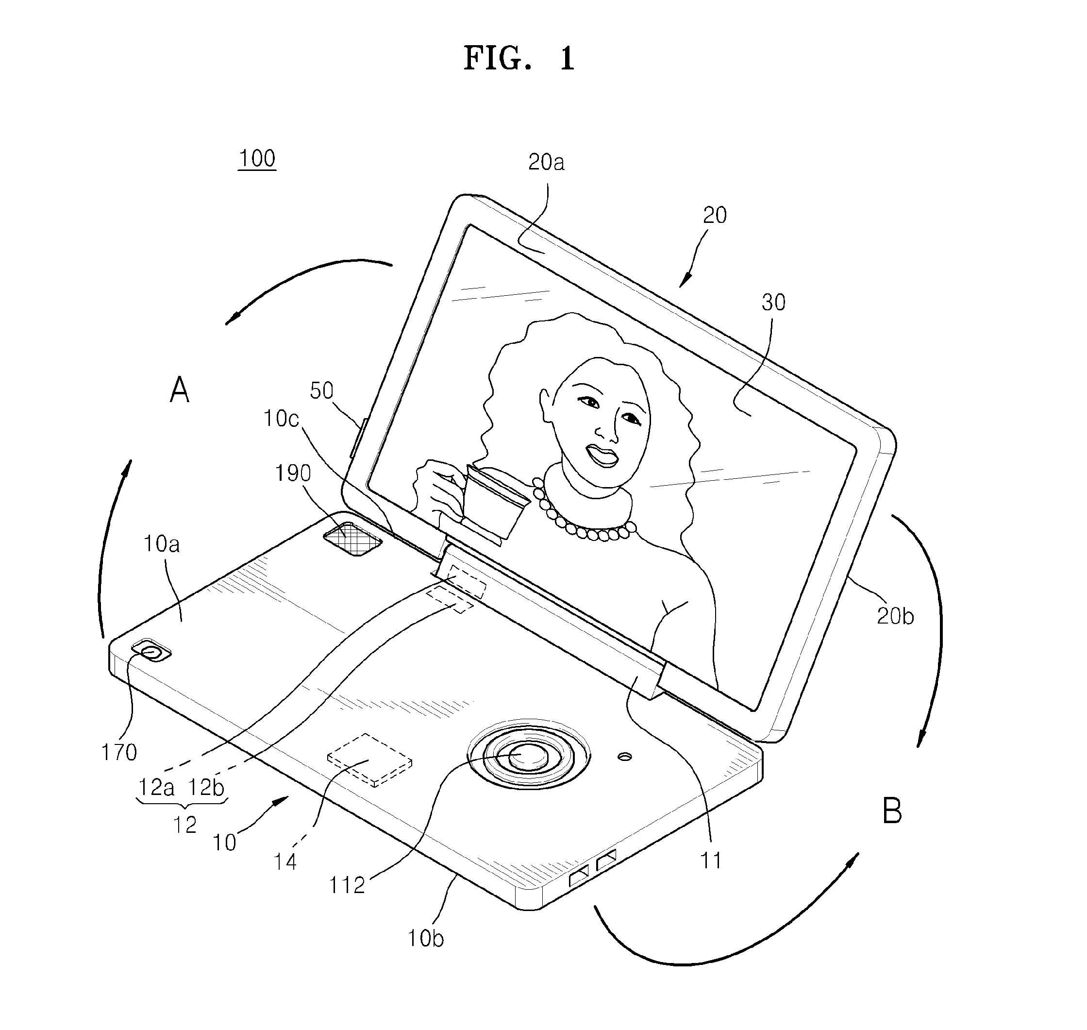
[0042]FIG. 1 is an isometric view of a camera 100 with a multi-function display, according to an embodiment of the invention.

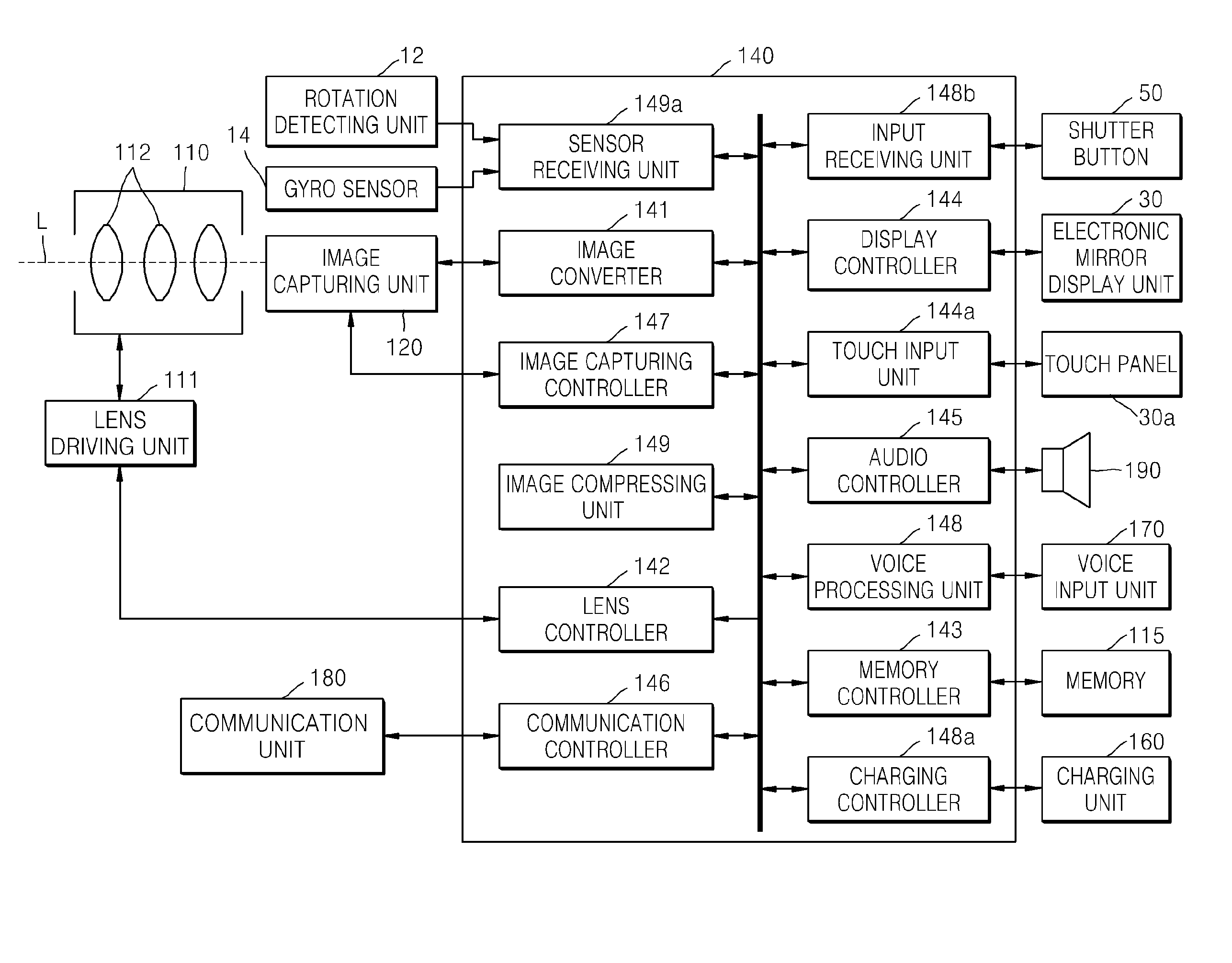
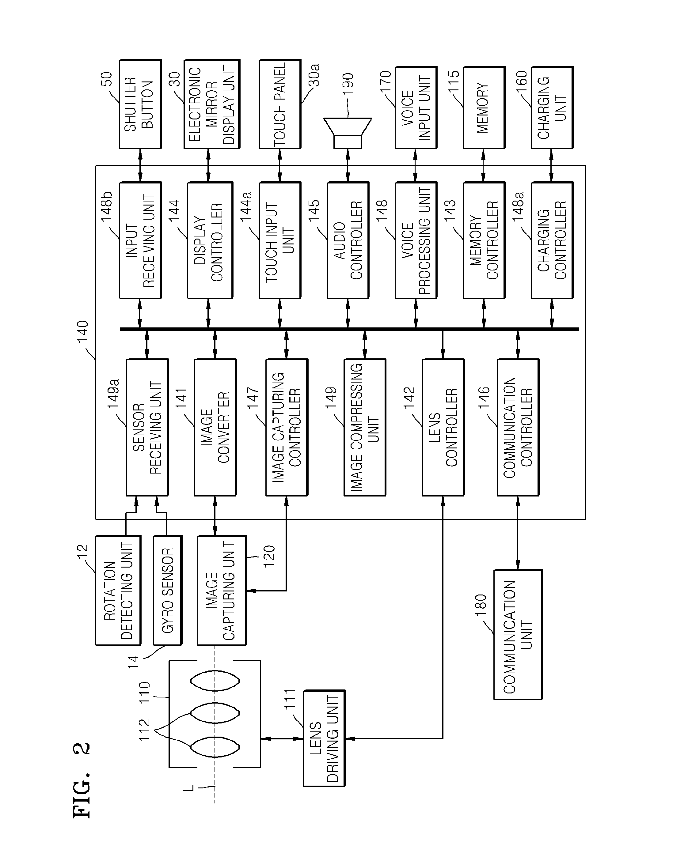
[0043]Referring to FIG. 1, the camera 100 with a multi-function display according to the present embodiment includes a first panel 10, a second panel 20 that is rotatably connected to the first panel 10, and an electronic mirror display unit 30 that is disposed on the second panel 20.

[0044]The second panel 20 is rotatably connected to the first panel 10 by interposing a hinge portion 11, which is connected to one edge 10c of the first panel 10, between the first panel 10 and the second panel 20. One end of the hinge portion 11 is rotatably connected to the first panel 10, and the other end of the hinge portion 11 is rotatably connected to the second panel 20. The first panel 10 and the second panel 20 may b...


PUM


Abstract

A camera is provided that includes a first panel including a plurality of lens units to capture an image, the lens units being disposed at one side of the first panel; a second panel that is rotatably connected to one edge of the first panel so that the first panel and the second panel rotate relative to each other between a first position contacting the one side of the first panel and a second position contacting the other side of the second panel; and an electronic mirror display unit to display an image if a signal is applied to the electronic mirror display unit and to reflect light if a signal is not applied to the electronic mirror display unit, the electronic mirror display unit being disposed at one side of the second panel corresponding to the one side of the first panel at the first position.

Description

CROSS-REFERENCE TO RELATED PATENT APPLICATION[0001]This application claims the priority benefit of Korean Patent Application No. 10-2011-0133996, filed on Dec. 13, 2011, in the Korean Intellectual Property Office, which is incorporated herein in its entirety by reference.BACKGROUND[0002]1. Field of the Invention[0003]The invention relates to a camera, and more particularly, to a camera with a multi-function display that may perform various functions, such as a mirror function, a display function, and the like.[0004]2. Description of the Related Art[0005]Cameras that may capture still images or moving images include a display that may display an image of a subject to be captured or a captured image.[0006]Korean Patent Application Publication No. 2005-0014561 discloses a camera with a rotating display. Thus, a user may observe the display from several angles. However, accommodation grooves need to be formed in a main body of the camera so as to install the display to be rotatable. Acc...

Claims


Application Information

Patent Timeline
IPC IPC(8): H04N5/222
CPCH04N5/23293H04N5/2251H04N23/531H04N23/631H04N23/00
Inventor KIM, DAE-MYUNGKUM, DONG-JUNOH, YUN-JEKIM, LAE-KYOUNG
Owner SAMSUNG ELECTRONICS CO LTD
Why Eureka
Try Eureka