Suspending device

a technology of suction device and suction plate, which is applied in the field of suction plate, can solve the problems of troublesome and difficult separation of magnetic field, and achieve the effect of effective fixation to a surfa

Inactive Publication Date: 2013-06-13
D R BIKE
View PDF3 Cites 7 Cited by
  • Summary
  • Abstract
  • Description
  • Claims
  • Application Information

AI Technical Summary

Benefits of technology

[0008]It is one object of the present invention to disclose a magnetic hanger (110) reversibly and effectively fixable to a surface (120), with a thin plane X-Y; said plane's main axis X comprising a first edge X1 and an opposite second edge X2; said hanger (110) characterized by having one or more non-flexible stiffening ribs (130) provided substantially in parallel to said plane's main axis Y, having a width Wx<<(X2−X1), such that said hanger (110) is provided with flexibility along said main axis X, whilst being non-flexible in other directions, ensuring that peeling of said hanger (110) from said surface (120) is restricted to a direction parallel to said main axis X starting from X1 or X2.

Problems solved by technology

If the magnetic hook is designed for hanging the heavy-weight object, the aforesaid force required for magnet separation can reach largeness so that magnet separation becomes difficult and troublesome.

Method used


Image

  • Suspending device
  • Suspending device
  • Suspending device

Examples


Embodiment Construction

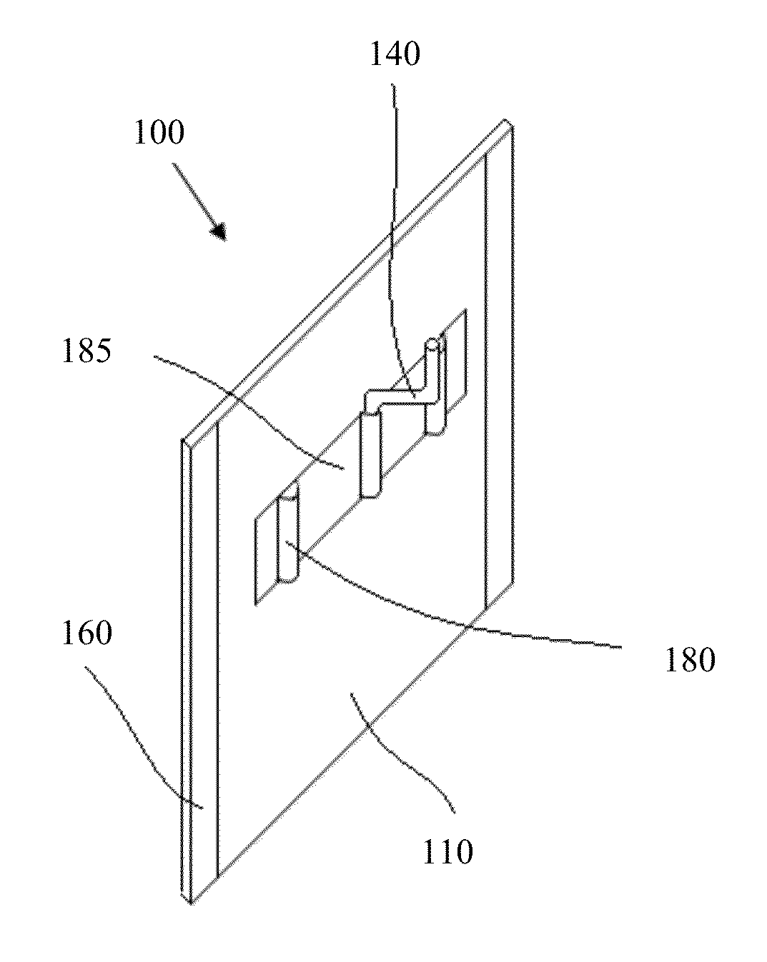
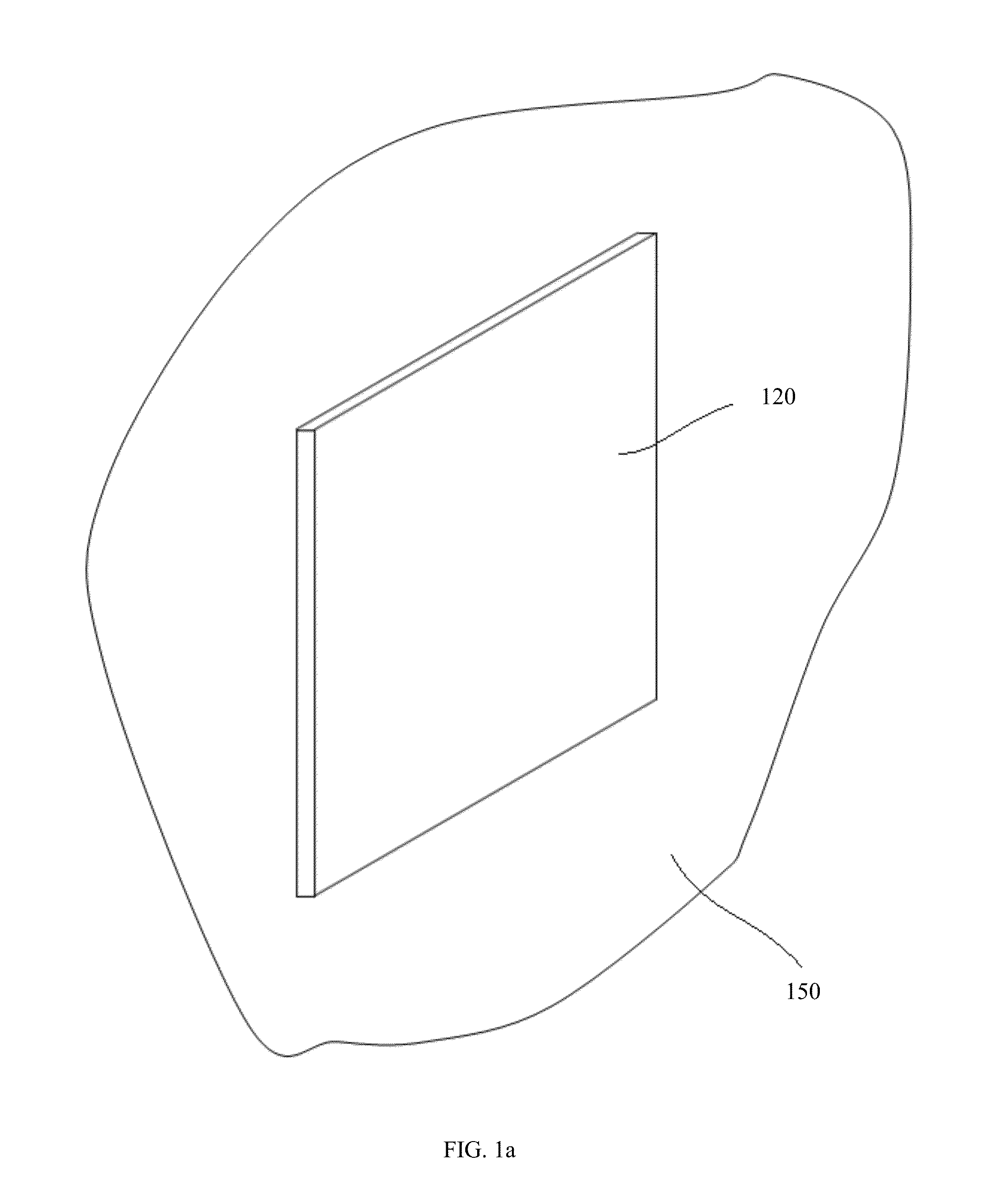
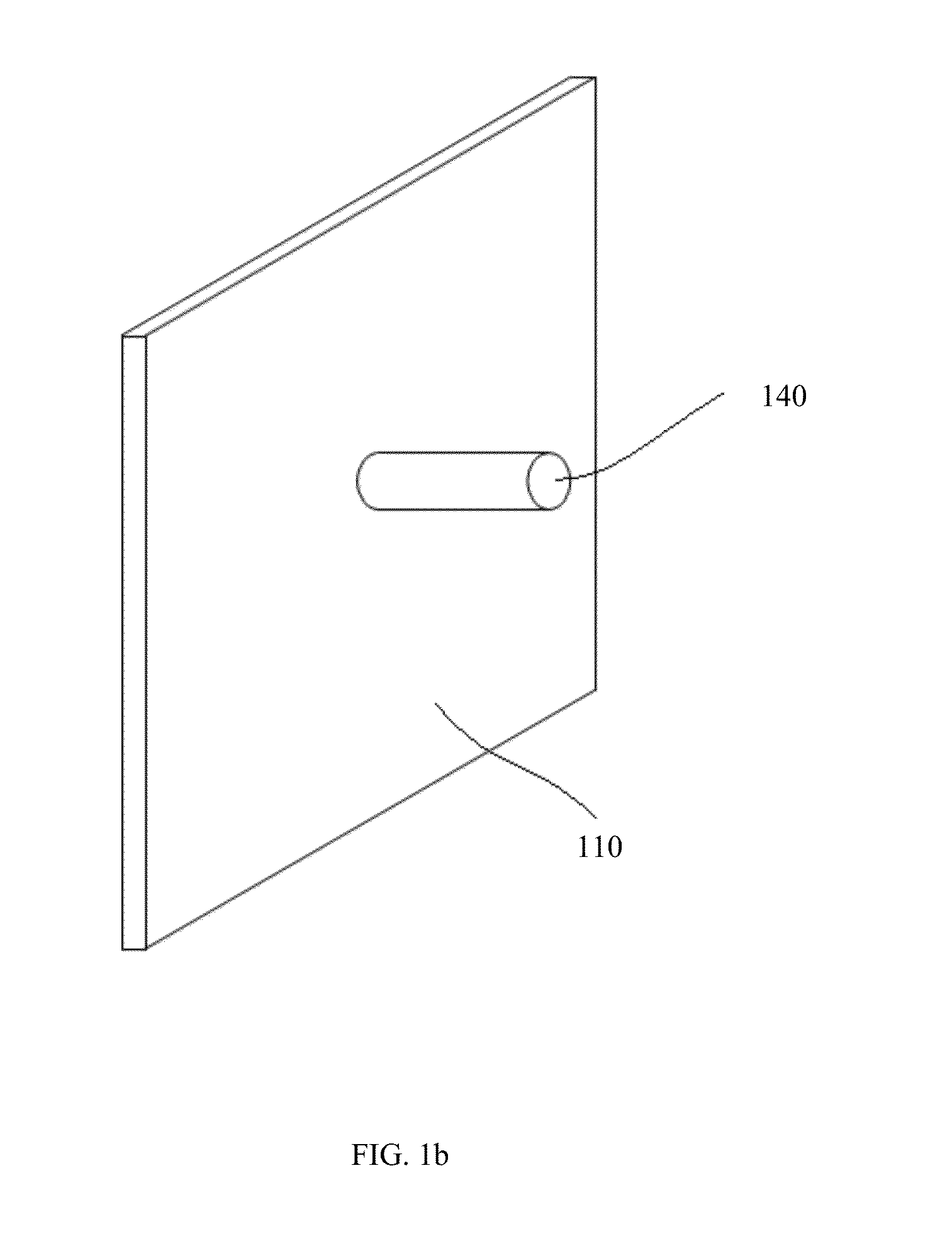
[0104]The following description is provided, alongside all chapters of the present invention, so as to enable any person skilled in the art to make use of said invention and sets forth the best modes contemplated by the inventor of carrying out this invention. Various modifications, however, are adapted to remain apparent to those skilled in the art, since the generic principles of the present invention have been defined specifically to provide a device 100 for temporarily suspending an object of interest by means of magnetically fixating the aforesaid object on—or to—a surface of interest 150.

[0105]It should be emphasized that a minimal force Fm of attractive interaction between the magnetizable surface 120 and the magnetic hanger 110 is defined by the following expression:

Fm>Fgkfr,

where:

[0106]Fg is a force applied to the magnetic hanger 110 by the hanged object due to gravity; kfr is a coefficient of friction between the magnetizable surface 120 and the magnetic hanger 110.

[010...


PUM

PropertyMeasurementUnit
forceaaaaaaaaaa
detachment forceaaaaaaaaaa
widthaaaaaaaaaa

Abstract

The present invention to disclose a magnetic hanger reversibly and effectively fixable to a surface with a thin plane X-Y The plane's main axis X comprising a first edge X1 and an opposite second edge X2. The hanger characterized by having one or more non-flexible stiffening ribs provided substantially in parallel to the plane's main axis Y, having a width Wx<<(X2−X1), such that the hanger provided with flexibility along the main axis X, whilst being non-flexible in other directions, ensuring that peeling of the hanger from the surface is restricted to a direction parallel to the main axis X, starting from X1 or X2.

Description

REFERENCE TO RELATED APPLICATIONS[0001]This application is a Continuation-In-Part of International Patent Application No. PCT / IL11 / 00652, filed on Aug. 10, 2011, now pending, and claims priority from U.S. Provisional Patent Application No. 61 / 344,512, filed on Aug. 12, 2010, now expired, both of which applications are hereby incorporated by reference in their entireties.FIELD OF THE INVENTION[0002]The present invention relates to a suspending device and, more specifically, to a magnetic suspending device provided with a temporarily attachable flexible member.BACKGROUND OF THE INVENTION[0003]Flexible permanent magnetic materials are often supplied in the form of sheets or rolls and have been commercially available for many years. These materials are typically prepared by mixing a powdered ferrite material with a suitable polymeric or plastic binder into a uniform mixture. The polymeric materials are often elastomers, and the process is therefore typically accomplished through the use...

Claims


Application Information

Patent Timeline
Patent Type & Authority Applications(United States)
IPC IPC(8): A47G29/02
CPCA47G1/17H01F1/117H01F7/0215Y10T29/4995A47G29/02Y10T428/24669H01F7/0252A47B97/001F16B2200/83F16B1/00F16M13/022
Inventor REINGEWIRTZ, DAVID
Owner D R BIKE
Why Eureka
Try Eureka