
Locking device for mechanical pieces, particularly for piece subjected to mechanical processing or similar

Active Publication Date: 2013-06-20
FCS SYST
View PDF14 Cites 1 Cited by
  • Summary
  • Abstract
  • Description
  • Claims
  • Application Information

AI Technical Summary

Benefits of technology

The invention is a locking device that is flexible, reliable, and cost-effective. Its main technical effects are improved ease of use and reliability.

Problems solved by technology

These known types of fixture are not free from drawbacks, which include the fact that since their dimensions and connection systems are standardized, they are scarcely flexible fixing systems, which therefore are not always suitable for locking particular mechanical pieces that do not have holes and geometries that are compatible with such fixtures.
If the mechanical piece to be processed in fact has particularly small geometry and / or dimensions, these known types of fixture cannot always be used, forcing the operator to provide custom fixtures capable of obviating the limitations of fixtures of the standardized type.
Even these custom fixtures of the known type are not free from drawbacks, which include the fact that if they are used to process small batches of pieces, the number of processed pieces is not such as to justify the production costs of such fixture.
Another drawback of known types of fixture, both standardized and custom, resides in that they do not allow correct fixing of the piece to be processed.
The simple bolting of the fixture to the piece and / or to the perforated plate very often is in fact insufficient to give the correct structural rigidity to the assembly formed by the piece, the fixture and the perforated plate, causing the piece to vibrate during processing and / or to move, reducing considerably the degree of precision of the processing.
A further drawback of known types of fixture is that their use requires a large number of bolting operations, which inevitably lead to an increase in the downtimes linked to machine stops, with consequent reductions in productivity.

Method used


Image

  • Locking device for mechanical pieces, particularly for piece subjected to mechanical processing or similar
  • Locking device for mechanical pieces, particularly for piece subjected to mechanical processing or similar
  • Locking device for mechanical pieces, particularly for piece subjected to mechanical processing or similar

Examples


Embodiment Construction

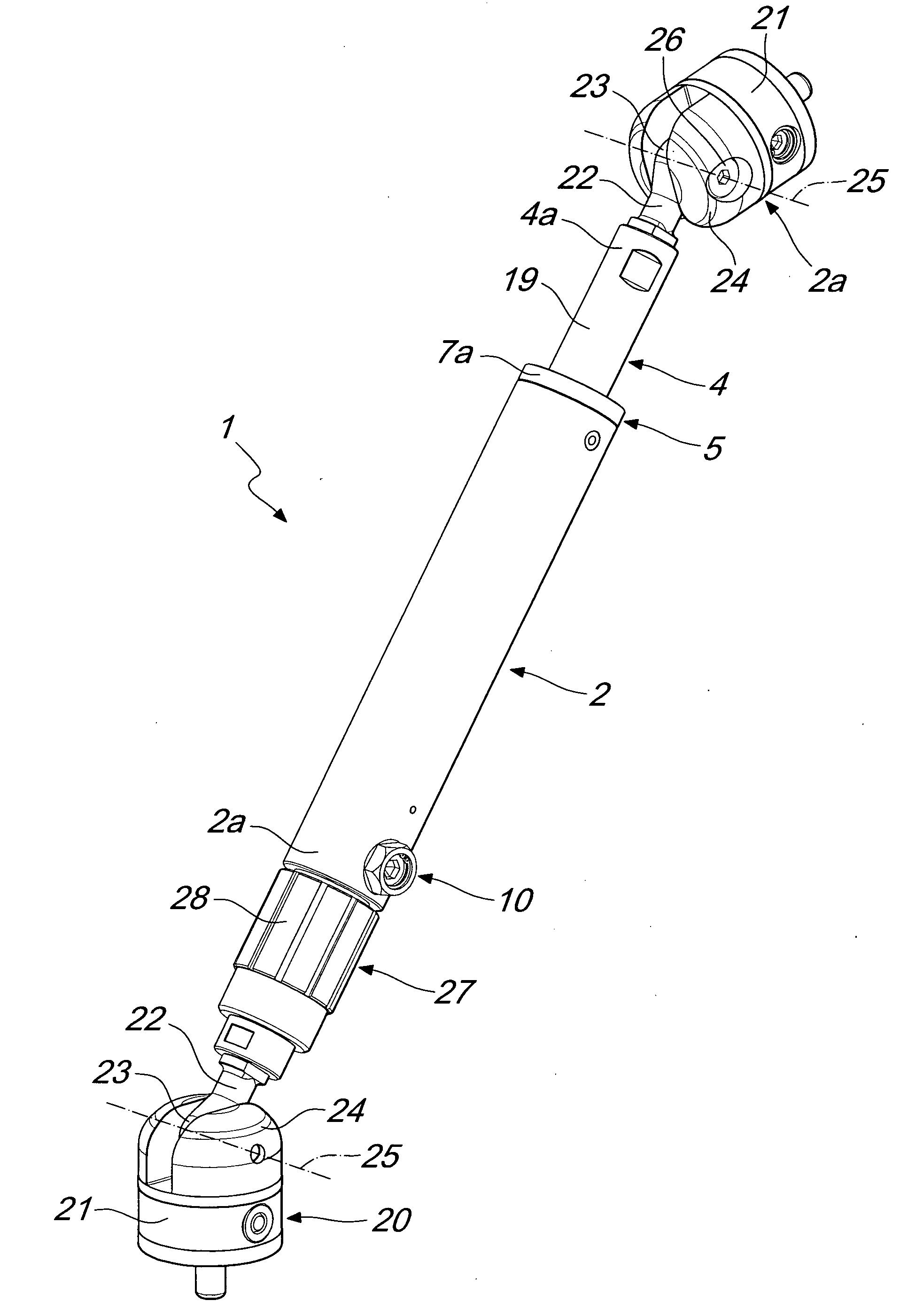
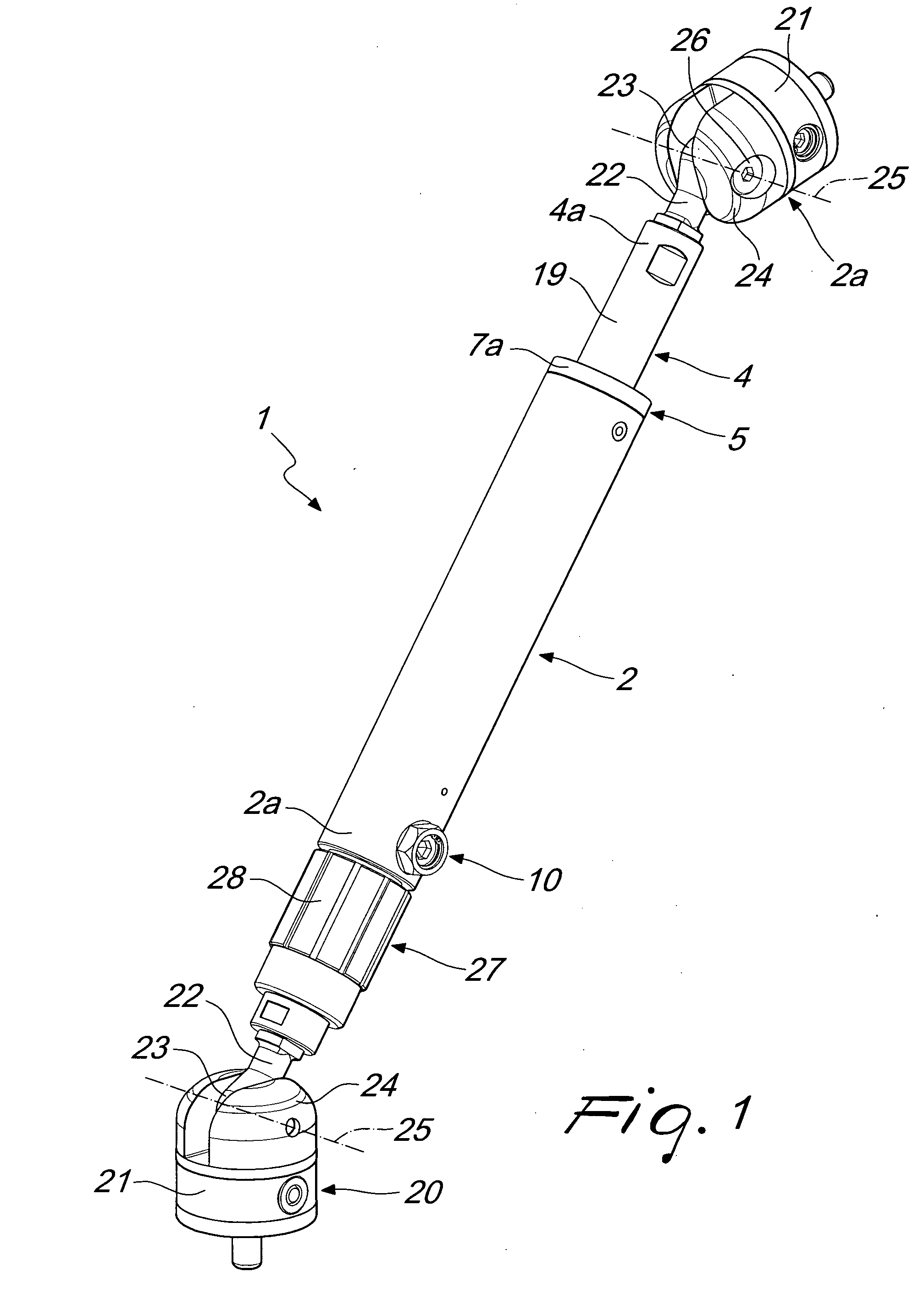
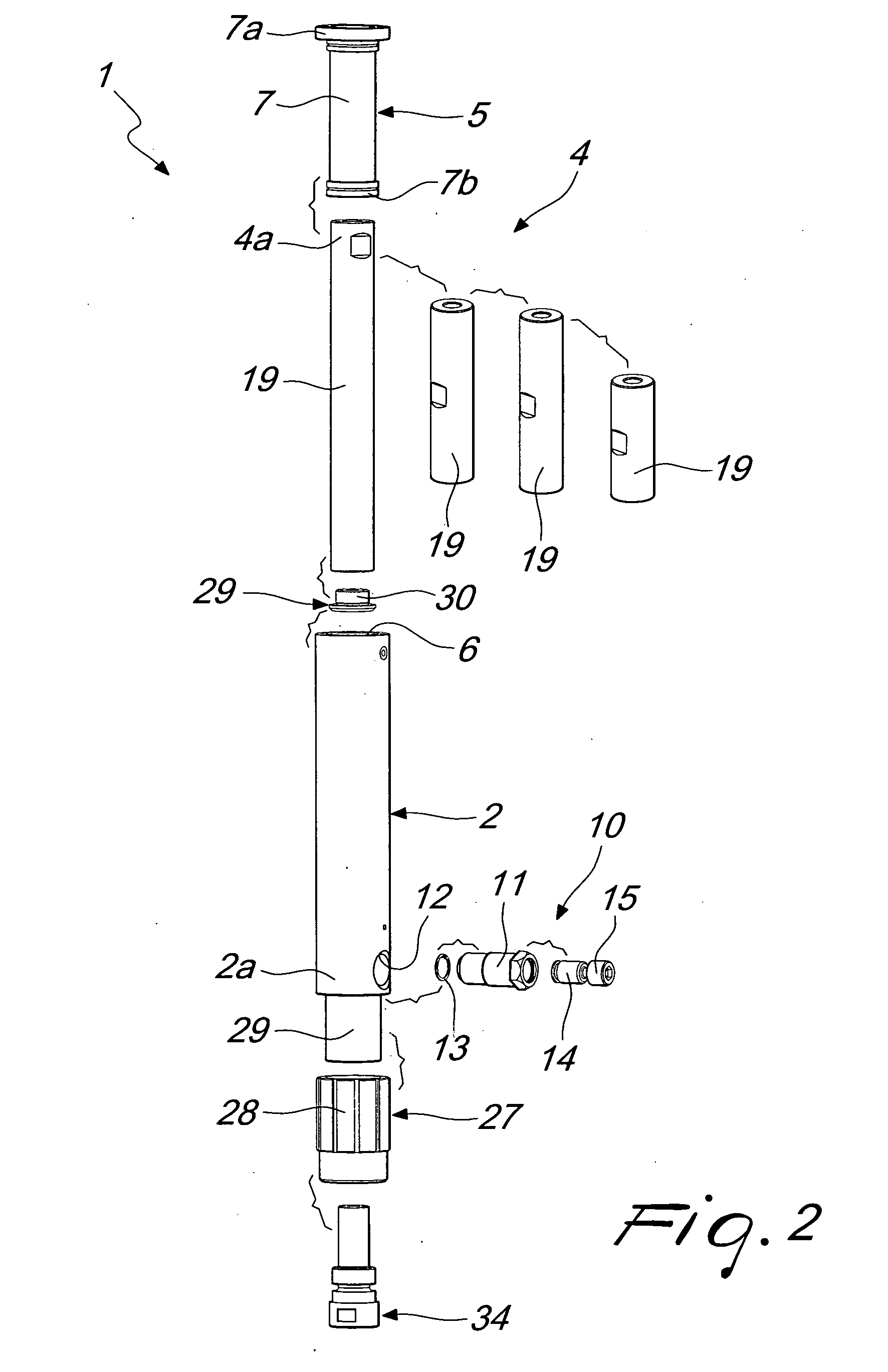
[0016]With reference to the figures, a locking device for mechanical pieces, particularly for pieces subjected to mechanical processing or similar, generally designated by the reference numeral 1, comprises at least one hollow body 2, also known as containment jacket, which forms a sliding seat 3, a movable stem 4, which is accommodated slidingly partially within the sliding seat 3, and radial expansion means 5, which are interposed between the hollow body 2 and the movable stem 4 and are adapted to mutually lock the two elements.

[0017]In greater detail, the hollow body 2 is substantially cylindrical and the sliding seat 3 is blind, having a single opening 6 through which the movable stem 4 protrudes partially from the hollow body 2.

[0018]Advantageously, the radial expansion means 5 comprise a tubular element 7, also known as expansion jacket, which is elastically deformable, is fitted slidingly on the movable stem 4 and is jointly accommodated with play within the sliding seat 3 so...


PUM


Abstract

A locking device for mechanical pieces, particularly for pieces subjected to mechanical processing or similar, comprising at least one hollow body that forms a sliding seat, a movable stem that is accommodated slidingly partially within the sliding seat of the hollow body and radial expansion elements which are interposed between the hollow body and the movable stem, the radial expansion elements being adapted to mutually lock the hollow body and the movable stem, the movable stem protruding partially from the hollow body with the hollow body and the movable stem jointly associable, at their free ends, by way of elements for connection, respectively, to a mechanical piece to be processed or a fixed part of a machine with which the mechanical piece is to be processed.

Description

TECHNICAL FIELD The present invention relates to a locking device for mechanical pieces, particularly for pieces subjected to mechanical processing or similar.BACKGROUND ART[0001]In the field of mechanical processing and similar, in particular as regards workshop fixtures, the need is known to be able to lock the piece to be processed with respect to the machine with which the mechanical piece is to be processed in a manner which is safe, repeatable and effective.[0002]This locking occurs, for example, by means of perforated L-shaped elements, which are fixed to the mechanical piece to be processed, by way of holes that are already present thereon, and to a perforated plate, which acts as a resting surface for processing and is fixed to the machine used for the processing.[0003]As an alternative, vises are also known which can be fixed to the perforated plate and are capable of clamping the piece to be processed so as to keep it motionless during processing. These known types of fix...

Claims


Application Information

Patent Timeline
IPC IPC(8): F16B7/14
CPCB23Q3/106Y10T403/32467F16B7/14B25B11/00B23Q3/062B23Q2703/02B23Q2703/08
Inventor CANUTO, ALMERINO
Owner FCS SYST
Features
  • Generate Ideas
  • Intellectual Property
  • Life Sciences
  • Materials
  • Tech Scout
  • Unparalleled Data Quality
  • Higher Quality Content
  • 60% Fewer Hallucinations
Learn More