Connectors providing haptic feedback

a technology of haptic feedback and connectors, applied in the direction of coupling device connections, coupling device details, coupling/disengagement of coupling parts, etc., can solve the problems of requiring expensive electronics to negotiate, and affecting signal quality or integrity

Active Publication Date: 2013-06-20
MOLEX INC
View PDF4 Cites 89 Cited by
  • Summary
  • Abstract
  • Description
  • Claims
  • Application Information

AI Technical Summary

Benefits of technology

The patent describes a connector that can be positioned in two different ways to connect with another connector. It includes a special communication unit and a magnet that aligns with the other connector's magnet when the two connectors are positioned in the second position. This alignment helps to improve the connection between the two connectors. When the two connectors are positioned in the first position, the magnets don't align and don't interfere with each other. This design allows for more flexibility in the positioning of the connectors and ensures a reliable connection between them.

Problems solved by technology

The patent text discusses the problem of connecting high-speed integrated circuits (ICs) on multiple printed circuit boards (PCBs) in electronic systems. Conventional methods like mechanical connectors create discontinuities in the signal path, leading to degraded signal quality or integrity. This requires expensive electronics and precise alignment, and may also wear out over time. The technical problem is how to connect ICs on multiple PCBs without introducing discontinuities and improving signal quality.

Method used


Image

  • Connectors providing haptic feedback
  • Connectors providing haptic feedback
  • Connectors providing haptic feedback

Examples


Embodiment Construction

[0020]Illustrative embodiments now will be described more fully hereinafter with reference to the accompanying drawings, in which some, but not all embodiments of connectors and connector systems are shown. Indeed, connectors and connector systems may be embodied in many different forms and should not be construed as limited to the embodiments set forth herein; rather, these embodiments are provided so that one skilled in the art can make and use the connectors and connector systems disclosed. Like numbers refer to like elements throughout.

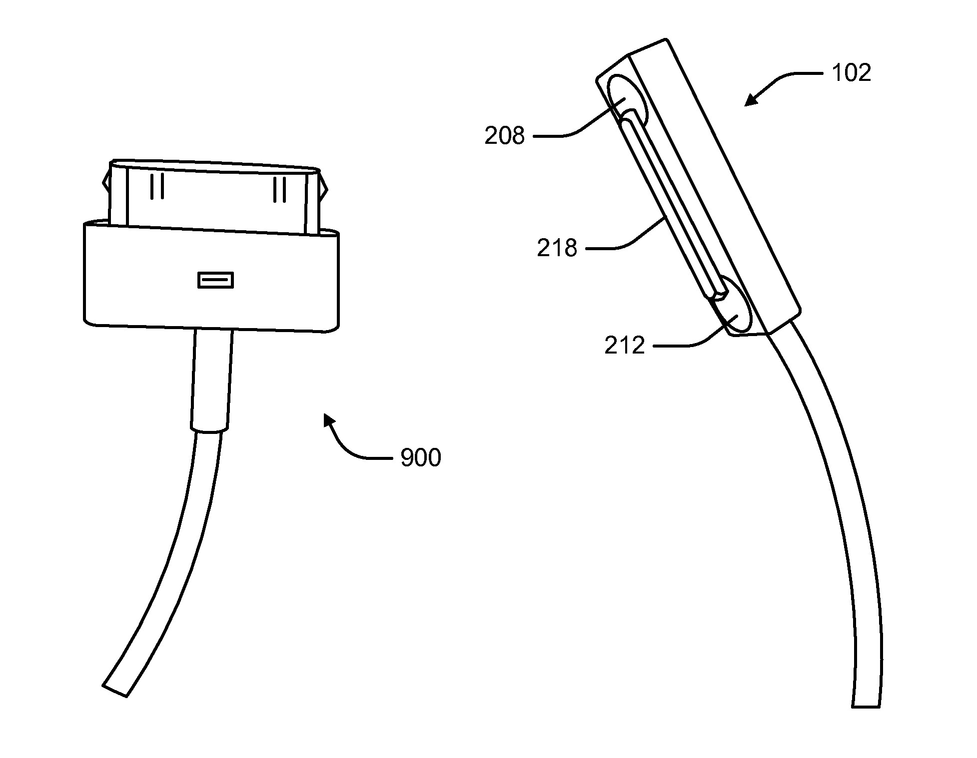
[0021]Connectors interconnect electronic devices and provide a pathway for signal and / or power transfer. Data transfer may be at very high rates. Connector systems are preferably easily manufactured, modular, and efficient. Examples of communication systems are disclosed in U.S. Pat. No. 5,621,913 and U.S. patent application Ser. No. 12 / 655,041. The disclosures of these and all other publications referenced herein are incorporated by reference in ...


PUM


Abstract

A first connector may include a housing defining a first connector face to be positioned in a first position or a second position proximate to a second connector face of a second connector. A first extremely high frequency (EHF) communication unit may be disposed in the housing for communicating with a second EHF communication unit of the second connector when the first connector face is positioned in first or second position relative to the second connector face. A first magnet may be disposed in the housing. The first magnet may align with and repel a second magnet disposed relative to the second connector face when the first connector face is positioned in the second position. The first magnet may be configured not to align with and not to repel the second magnet when first connector face is positioned in the first position relative to the second connector face.

Description


Claims


Application Information

Patent Timeline
Owner MOLEX INC
Why Eureka
Try Eureka