Communication system with a beamformed control channel and method of system control

a communication system and control channel technology, applied in the field of cellular communication systems, can solve the problems of inability to attend, inability to control, and inability to control downlink beamforming from an adaptive array of antenna elements co-located with each base site controller

Inactive Publication Date: 2001-12-11
MOTOROLA INC
View PDF11 Cites 234 Cited by
  • Summary
  • Abstract
  • Description
  • Claims
  • Application Information

AI Technical Summary

Problems solved by technology

Furthermore, all mobile units in a particular coverage area have access to this RACH all the time, and so contentions may arise in the event that two mobiles simultaneously attempt to transmit on the RACH.
Specifically, a base station controller (or a base transceiver station) is unable to resolve these simultaneous transmissions, and is therefore unable to isolate and is hence unable to attend

Method used


Image

  • Communication system with a beamformed control channel and method of system control
  • Communication system with a beamformed control channel and method of system control
  • Communication system with a beamformed control channel and method of system control

Examples


Embodiment Construction

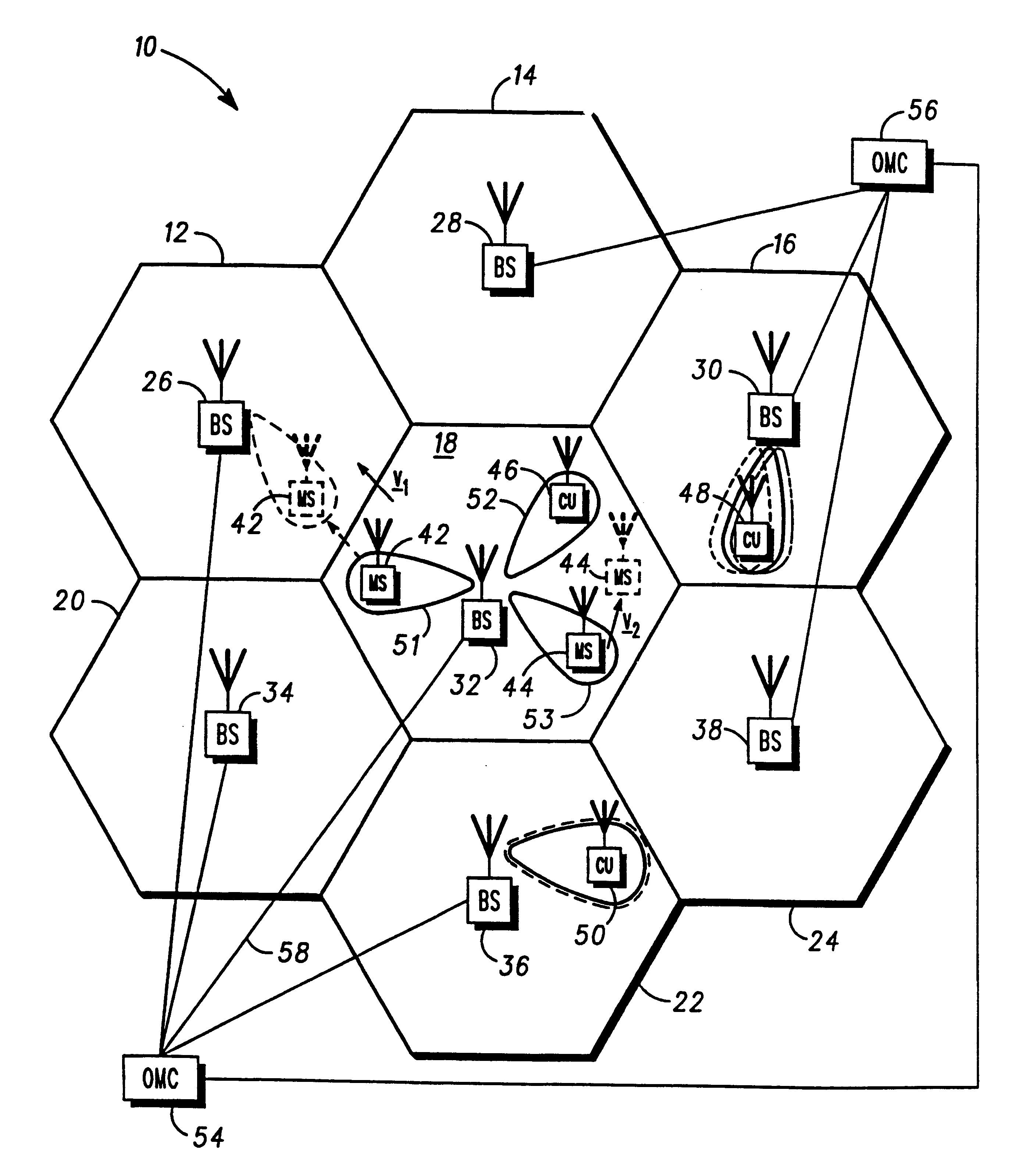
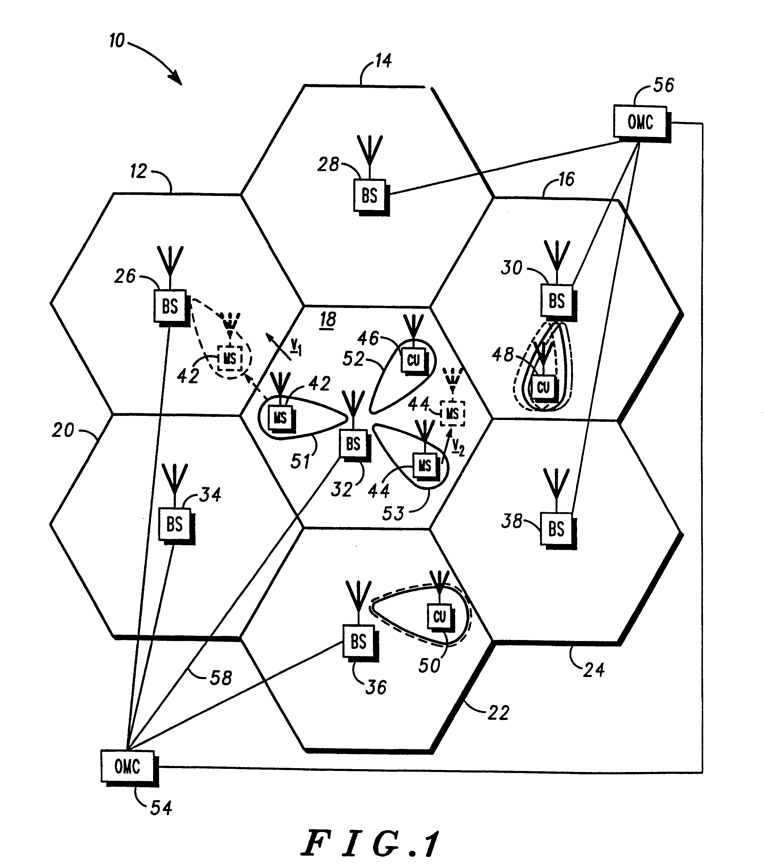
Turning to FIG. 1, a block diagram of a communication system 10 according to a preferred embodiment of the present invention is defined by a plurality of adjoining cells 12-24 that are conventionally represented in a hexagonal pattern. Each cell 12-24 contains base station equipment 26-38 that is centrally located to optimise communication coverage in each cell and which equipment includes an adaptive array of antenna elements. In this description, the generic term "base station equipment" will be used to refer to a base station controller, a base transceiver station or an appropriate combination, and is indicative of a communication unit that has control logic capable of supporting and routing calls between both mobile and fixedly located voice or data communication equipment (typically arranged to operate at radio frequencies).

Communication units 42-50, such as mobile telephone and mobile data units 42-44, are dispersed throughout the geographic region of the communication system ...


PUM


Abstract

To reduce interference in a communication system (10), a communication unit (42-50) is arranged to initiate establishment of a radio frequency communication with a base station (26-38) by transmitting a system access request on a dedicated, wide area control channel. Upon receipt of the system access request, a base station (32) of the communication system of FIG. 1 responds by forming a narrowbeam control channel to the communication unit and transmitting system control information to the communication unit on the narrowbeam control channel, the system control information transmitted from the array of antenna elements and arranged to identify a narrowbeam communication resource for use in the radio communication. The communication unit (42-50), upon receiving the system control information, then configures itself to utilise the narrowbeam communication resource for the radio communication.

Description

This invention relates, in general, to a communication system with a beamformed control channel and particularly to a method of system control in a communication system having an adaptive antenna array.SUMMARY OF THE PRIOR ARTCellular communication systems, generally, are comprised of many adjacent "cells" each administered by a base station controller. Usually, each base station controller will control a number of base transceiver stations responsible for administering individual sectors within each cell. Mobile units affiliated to a particular system (which could be a time or frequency division system) are free to move between cells and are in controlled communication with, principally, only one base transceiver station at any one instance in time, and each mobile unit is thus subject to a hand-off mechanism between base transceiver stations (and occasionally base station controllers) in adjacent sectors (or cells, respectively) when the mobile unit transitions a nominal boundary ...

Claims


Application Information

Patent Timeline
IPC IPC(8): H04Q7/36H04Q7/38H04B7/10H01Q3/26H04B7/26H04W16/24H04W16/28H04W24/00H04W28/06H04W64/00H04W74/00H04W76/02
CPCH04W16/28H04W72/046H04W16/24H04W24/00H04W28/06H04W64/00H04W72/042H04W74/00H04W72/23
Inventor CRICHTON, PAULHOWARD, PAULANDERSON, NICHOLASROBINSON, WILLIAM
Owner MOTOROLA INC
Why Eureka
Try Eureka