Catalyst-thermoelectric generator integration

a generator and catalyst technology, applied in the field of catalysts and thermoelectric generators, can solve the problems of gas side being one of the main limiting factors, affecting the performance of thermoelectric devices, and the thermal resistance created by the ceramic substrate of the module,

Inactive Publication Date: 2013-07-25
GENTHERM INC
View PDF7 Cites 82 Cited by
  • Summary
  • Abstract
  • Description
  • Claims
  • Application Information

AI Technical Summary

Problems solved by technology

Often, the thermal resistance created by the ceramic substrates of the module, as well as by the interfacial material used to connect them to the heat exchangers, is quite large and detrimental to the performance of the thermoelectric device.
In addition, for liquid-to-gas TE applications, the gas side ...

Method used


Image

  • Catalyst-thermoelectric generator integration
  • Catalyst-thermoelectric generator integration
  • Catalyst-thermoelectric generator integration

Examples


Embodiment Construction

[0079]Although certain configurations and examples are disclosed herein, the subject matter extends beyond the examples in the specifically disclosed configurations to other alternative configurations and / or uses, and to modifications and equivalents thereof. Thus, the scope of the claims appended hereto is not limited by any of the particular configurations described below. For example, in any method or process disclosed herein, the acts or operations of the method or process may be performed in any suitable sequence and are not necessarily limited to any particular disclosed sequence. Various operations may be described as multiple discrete operations in turn, in a manner that may be helpful in understanding certain configurations; however, the order of description should not be construed to imply that these operations are order dependent. Additionally, the structures, systems, and / or devices described herein may be embodied as integrated components or as separate components. ...


PUM


Abstract

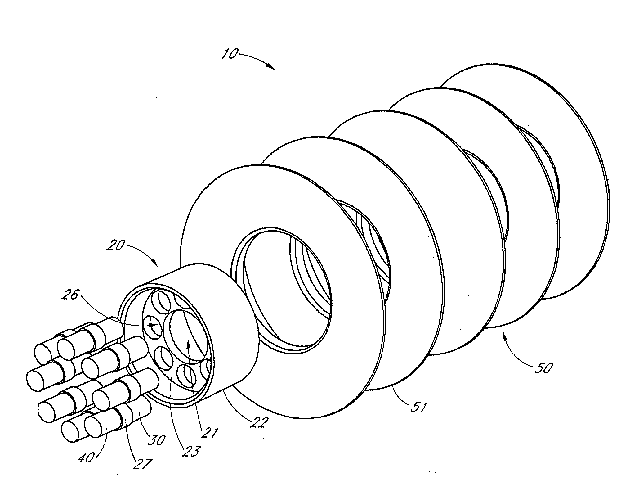
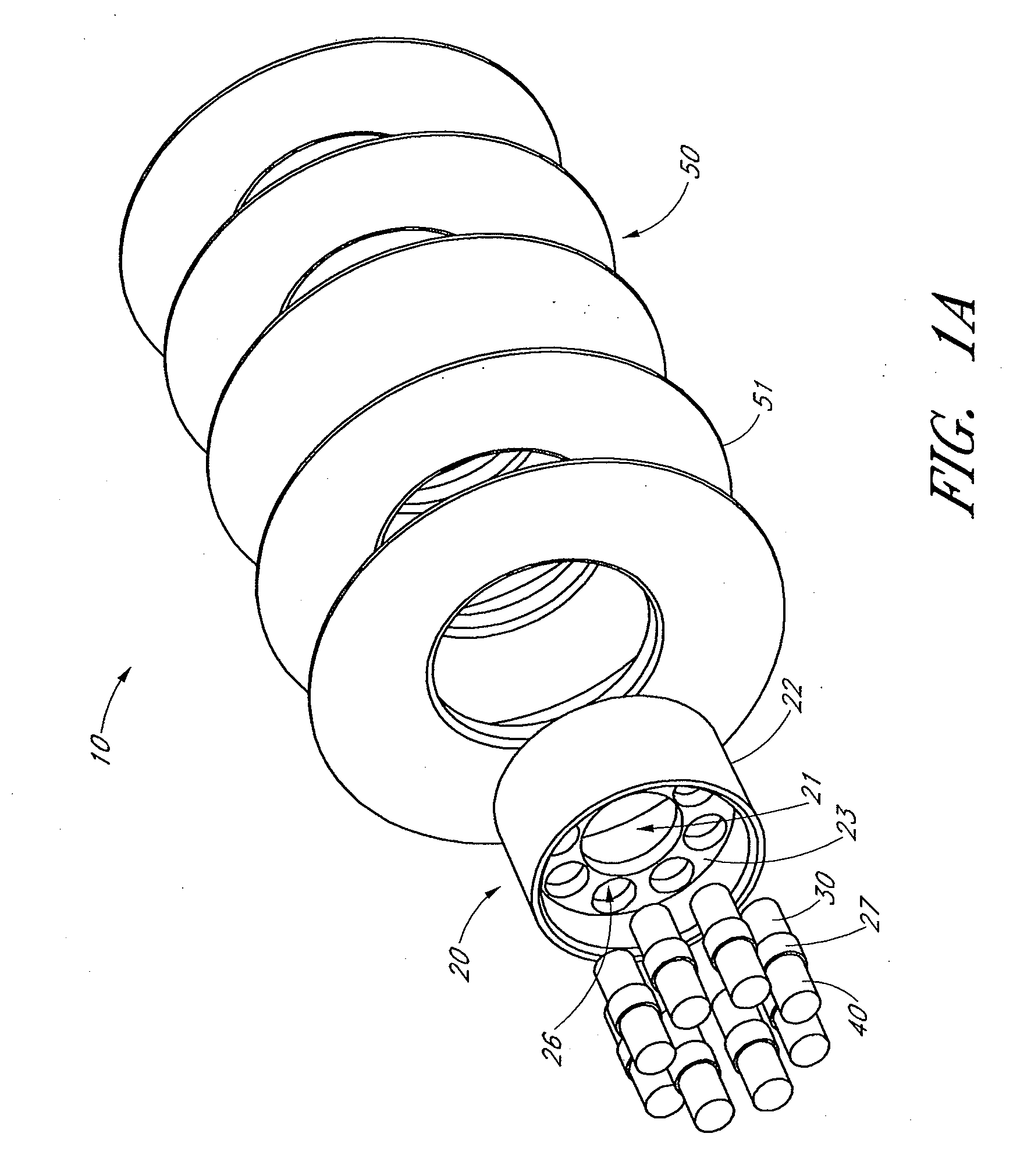
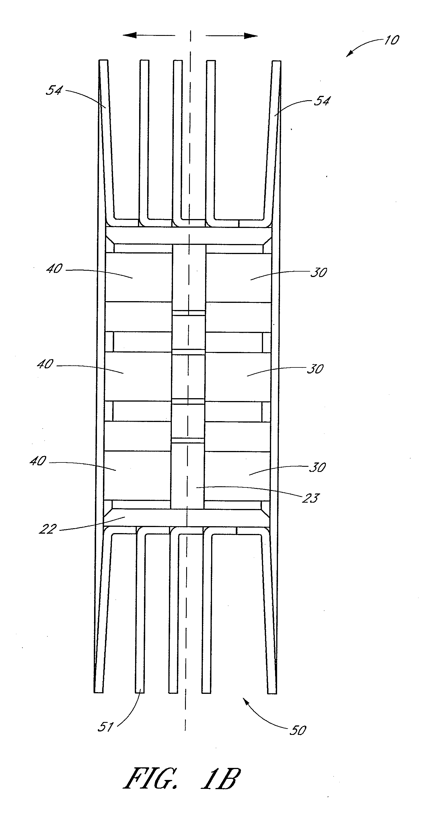
A thermoelectric system is provided which includes at least one tubular conduit configured to be in thermal communication with at least one first fluid flowing through the at least one tubular coolant conduit in a first direction. A plurality of thermoelectric elements can be in thermal communication with the at least one tubular conduit. A heat exchanger in thermal communication with the plurality of thermoelectric elements is configured to be in thermal communication with at least one second fluid and to surround at least a portion of the tubular conduit and plurality of thermoelectric elements. The heat exchanger can include at least one coating configured to catalyze reactions of at least one portion of the second fluid.

Description

CROSS-REFERENCE TO RELATED APPLICATIONS[0001]This application claims the benefit of priority from U.S. Provisional Appl. No. 61 / 589,088, filed Jan. 20, 2012 and incorporated in its entirety by reference herein. This application is also related to U.S. application Ser. No. 13 / 498,237, entitled “Cartridge-Based Thermoelectric Systems,” filed Jun. 5, 2012, which claims the benefit of priority to U.S. Provisional Appl. No. 61 / 493,871, filed Jun. 6, 2011, U.S. Provisional Appl. No. 61 / 493,926, filed Jun. 6, 2011, U.S. Provisional Appl. No. 61 / 493,935, filed Jun. 6, 2011, and U.S. Provisional Appl. No. 61 / 566,194, filed Dec. 2, 2011, each of which is incorporated in its entirety by reference herein. This application is also related to U.S. patent application Ser. No. 13 / 489,192, entitled “Systems and Method for Reducing Current and Increasing Voltage in Thermoelectric Systems,” filed on Jun. 5, 2012 and incorporated in its entirety by reference herein. This application is also related to ...

Claims


Application Information

Patent Timeline
IPC IPC(8): H01L35/30
CPCF01N5/025F01N2570/12H01L35/30F01N3/103F01N2610/03F01N13/009Y02T10/16Y02T10/26F01N3/2006F01N3/2013F01N3/2053F01N2410/02F01N3/0835F01N3/10F01N3/36F01N2240/02F01N2570/10H01L35/32Y02T10/12H10N10/17H10N10/13
Inventor RANALLI, MARCOLAGRANDEUR, JOHN
Owner GENTHERM INC
Why Eureka
Try Eureka