Supercharge Your Innovation With Domain-Expert AI Agents!

Pneumatic tire

a technology of pneumatic tires and rubber, applied in the field of pneumatic tires, can solve the problems of heat generation, heat accumulation, and deterioration of rubber, and achieve the effect of preventing rubber deterioration and increasing the thickness of rubber

Active Publication Date: 2013-08-01
BRIDGESTONE CORP
View PDF10 Cites 4 Cited by
  • Summary
  • Abstract
  • Description
  • Claims
  • Application Information

AI Technical Summary

Benefits of technology

The present invention provides a pneumatic tire with an optimized distance between the ply cords and prevents rubber deterioration caused by heat accumulation and heat generation due to an increase in the thickness of rubber. This is achieved by notching a widthwise outer skin rubber inwardly in the width direction of the tire to form a notched portion on the widthwise outer skin rubber situated widthwise outside of a region where the distance between ply cords of the carcass body section and the carcass folded section gradually increases. This helps to prevent rubber deterioration without sacrificing other performances such as cutting resistance performance.

Problems solved by technology

However, this technique deteriorates the rubber due to an increase in heat generation and heat accumulation caused by an inevitable increase in the thickness of the rubber at the portion containing the position where the distance between the ply cords changes from a gradual increase to a gradual decrease (in other words, the maximal position of the distance between the ply cords).

Method used


Image

  • Pneumatic tire
  • Pneumatic tire
  • Pneumatic tire

Examples


example 1

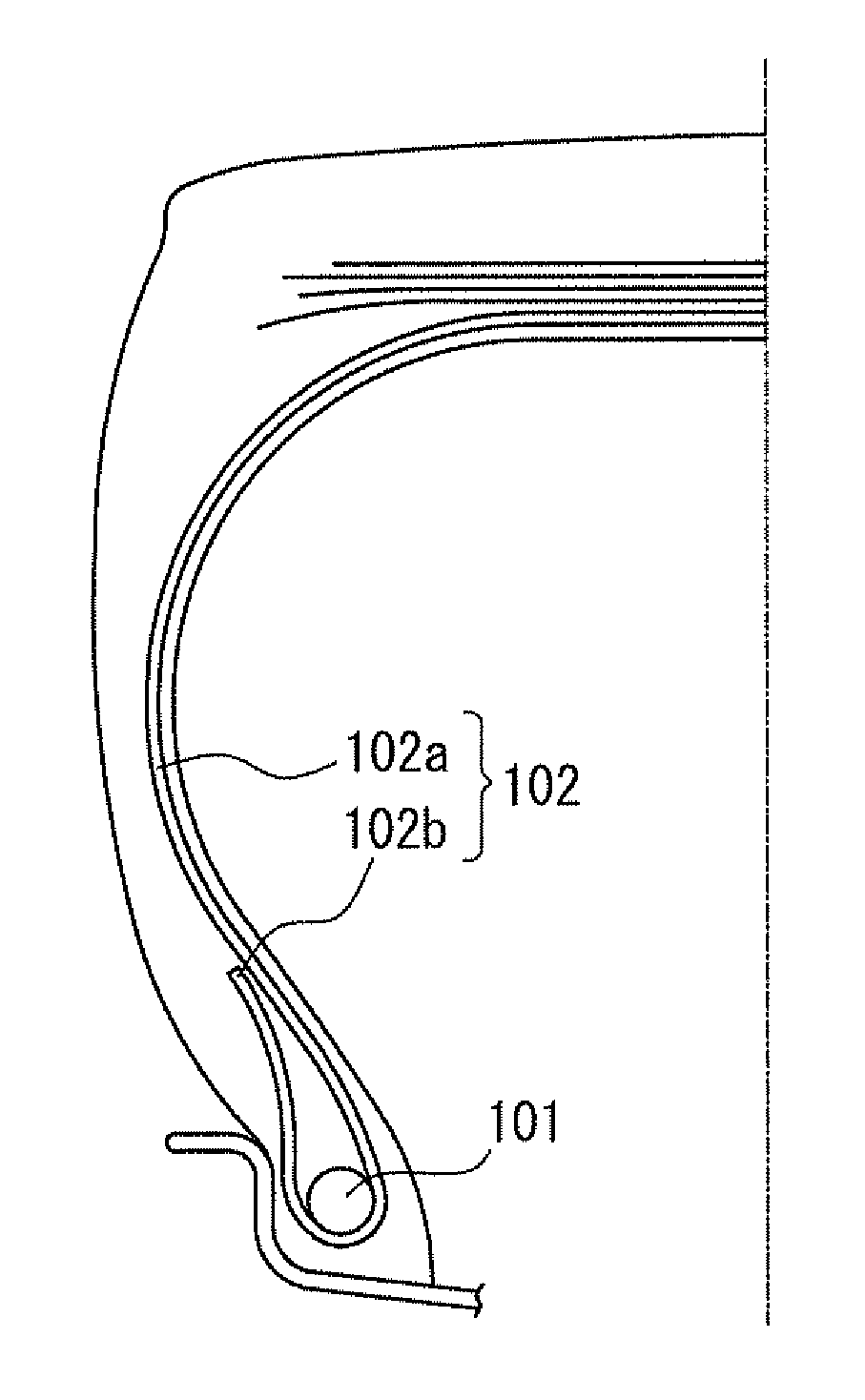
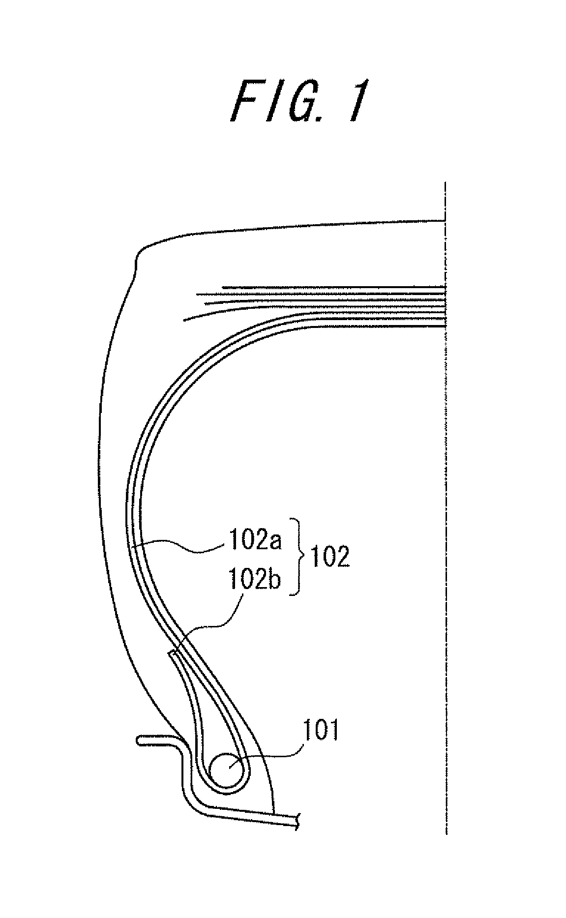
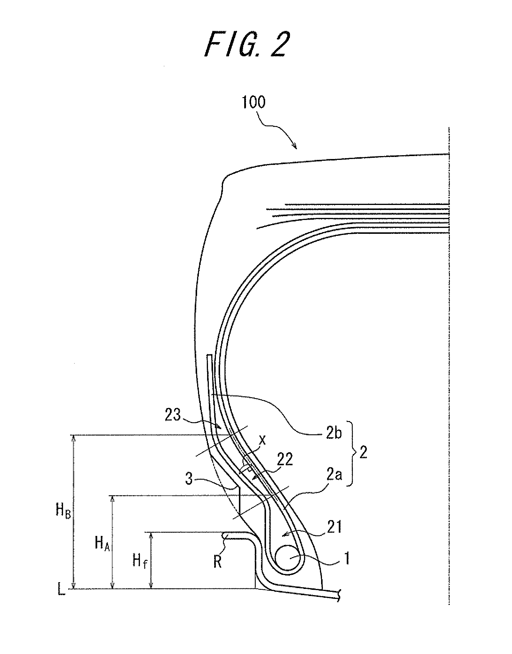
[0044]A pneumatic tire having the tire size of 59 / 80R63 and the structure shown in FIG. 2 has been prepared. The pneumatic tire thus prepared includes a pair of bead cores and a carcass formed of a ply, the ply consists of a carcass body section extending toroidally between the pair of bead cores and a carcass folded section extending from the carcass body section and folded around the bead cores. The carcass includes a first portion in which a distance between ply cords of the carcass body section and the carcass folded section gradually decreases from a position of the bead cores toward outside in a radial direction of the tire, a second portion in which the distance between the ply cords gradually increases from the first portion toward outside in a radial direction of the tire, and a third portion in which the distance between the ply cords gradually decreases from the second portion toward outside in a radial direction of the tire. Furthermore, a notched portion is provided on ...

example 2

[0045]A pneumatic tire is prepared in the same manner as in Example 1 except that the cross-sectional shape of the notched portion in the width direction of the tire is set to be trapezoidal shape.

example 3

[0046]A pneumatic tire is prepared in the same manner as in Example 1 except that the notched portion is set in a circular arc sectional shape with a curvature radius of 1 or more in the width direction of the tire.


PUM


Abstract

A pneumatic tire includes a carcass having a first portion in which a distance between ply cords of a carcass body section and a carcass folded section gradually decreases from a position of a bead core toward outside in a radial direction of the tire, a second portion in which the distance between the ply cords gradually increases from the first portion toward outside in the radial direction of the tire, and a third portion in which the distance between the ply cords gradually decreases from the second portion toward outside in the radial direction of the tire. A notched portion is provided on a widthwise outer skin rubber of the carcass folded section of the second portion by notching the widthwise outer skin rubber inwardly in the width direction of the tire.

Description

TECHNICAL FIELD[0001]The present invention relates to a pneumatic tire, particularly relates to a pneumatic tire for heavy duty vehicles such as trucks and buses.RELATED ART[0002]For example, as illustrated in FIG. 1, a conventional pneumatic tire includes a carcass 102 formed of a ply extending toroidally between a pair of bead cores 101. The carcass 102 of the pneumatic tire consists of a carcass body section 102a extending toroidally between the pair of bead cores 101 and a carcass folded section 102b extending from the carcass body section 102a and folded around the bead core 101. It should be noted that the distance between the carcass body section 102a and the carcass folded section 102b (the distance between the ply cords) in general gradually decreases from a position of the bead cores 101 toward outside in the radial direction of the tire.[0003]In Patent Document 1, the techniques of optimizing the thickness and shape of the rubber between the carcass body section 102a and ...

Claims


Application Information

Patent Timeline
Patent Type & Authority Applications(United States)
IPC IPC(8): B60C15/00
CPCB60C15/0036B60C15/024B60C15/0009B60C13/02B60C15/00B60C15/0063
Inventor SASAKI, AKIRA
Owner BRIDGESTONE CORP
Features
  • R&D
  • Intellectual Property
  • Life Sciences
  • Materials
  • Tech Scout
  • Unparalleled Data Quality
  • Higher Quality Content
  • 60% Fewer Hallucinations
Learn More