
Method For Measuring Remote Field Eddy Current Thickness In Multiple Tubular Configuration

a technology of remote field eddy current and measurement method, which is applied in the direction of electromagnetic wave detection, instruments, material magnetic variables, etc., can solve the problems of false thickness change, difficult identification, and environmental and economic risk for operators

Active Publication Date: 2013-08-01
HALLIBURTON ENERGY SERVICES INC
View PDF100 Cites 86 Cited by
  • Summary
  • Abstract
  • Description
  • Claims
  • Application Information

AI Technical Summary

Benefits of technology

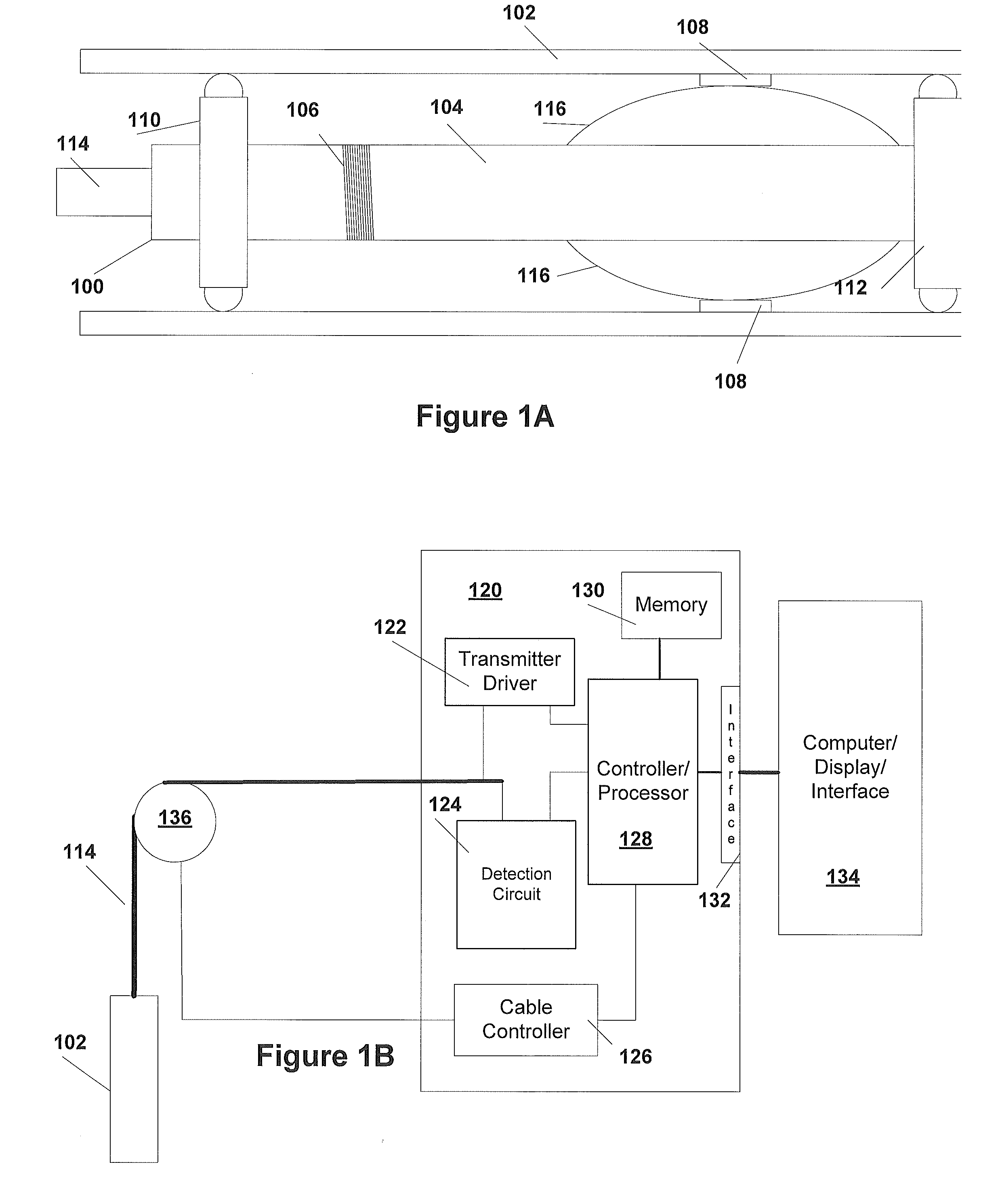
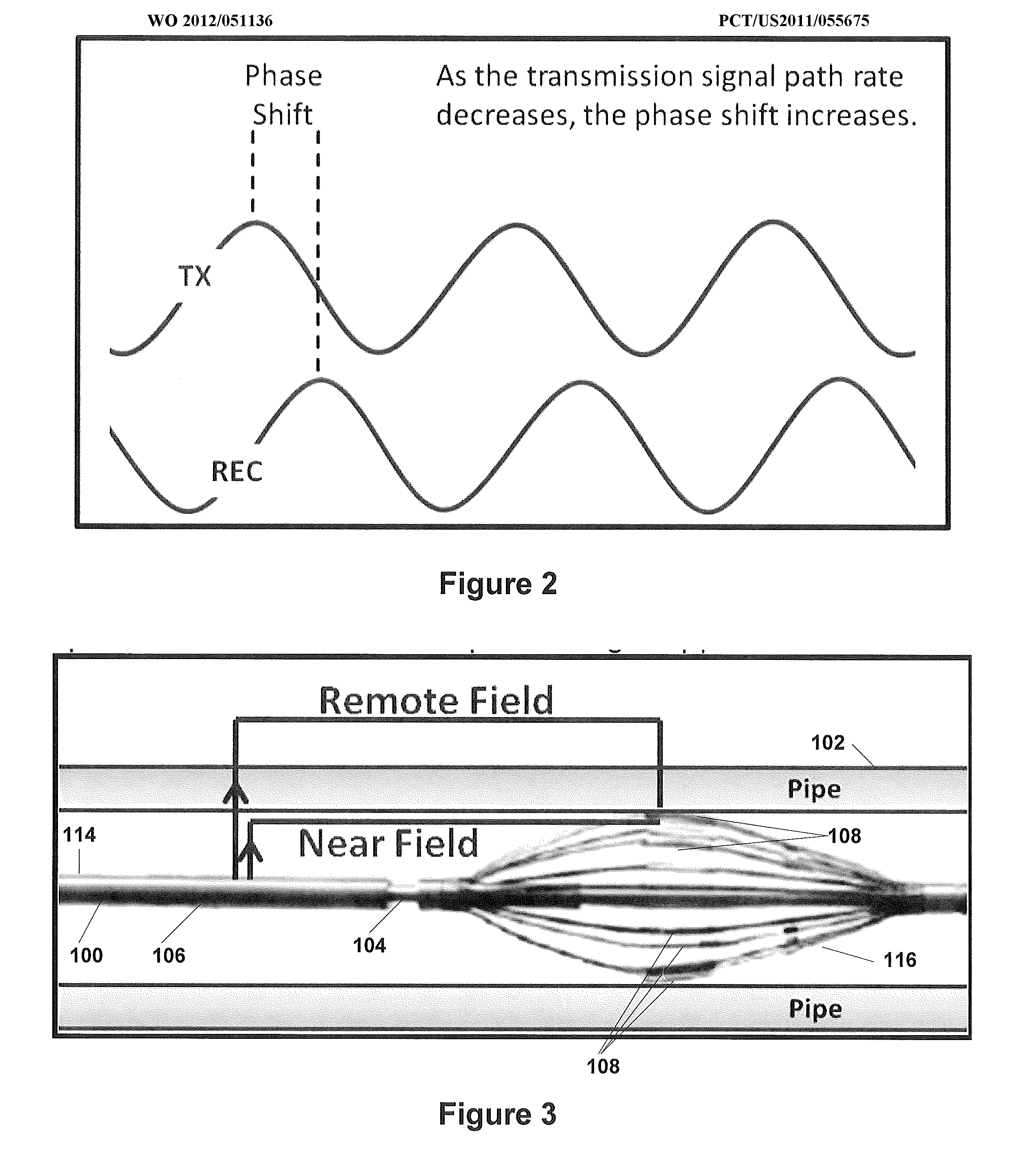
The present invention is about inspecting a well tubular, specifically a pipe. A method is provided where a probe is lowered into the pipe, and the probe includes a transmitter and at least one detector separated from the transmitter by a distance equal to or greater than twice the diameter of the pipe. A driving signal is provided to the transmitter, and detector signals are received from the detectors. The phase shift between the detector signals and the driving signal is determined, which can be used to identify faults along the pipe. A partial saturation step can also be performed. A system for testing a pipe is also disclosed, which includes a controller and a probe coupled to the controller, the probe including a transmitter and one or more detectors separated from the transmitter by a distance at least twice that of the inner diameter of the pipe. The system can also have a detection circuit and a processor to determine the phase of signals received at the detectors relative to the signal provided by the transmitter.

Problems solved by technology

Aging oilfield tubular create environmental and economic risk to operators.
These magnetic anomalies create false thickness changes that can be difficult to identify and are often assumed to be pipe defects.
False defects reduces confidence in the analysis of the results.
Aging oilfield tubular create environmental and economic risk to operators.

Method used


Image

  • Method For Measuring Remote Field Eddy Current Thickness In Multiple Tubular Configuration
  • Method For Measuring Remote Field Eddy Current Thickness In Multiple Tubular Configuration
  • Method For Measuring Remote Field Eddy Current Thickness In Multiple Tubular Configuration

Examples


Embodiment Construction

[0031]In the following description, specific details are set forth describing some embodiments of the present invention. It will be apparent, however, to one skilled in the art that some embodiments may be practiced without some or all of these specific details. The specific embodiments disclosed herein are meant to be illustrative but not limiting. One skilled in the art may realize other material that, although not specifically described here, is within the scope and the spirit of this disclosure.

[0032]Techniques according to some embodiments of the present invention are capable of separating and quantifying the thickness of each of a multiple tubular arrangement. Some techniques according to embodiments of the present invention can also be utilized to identify permeability induced false responses and allow for a qualitative analysis.

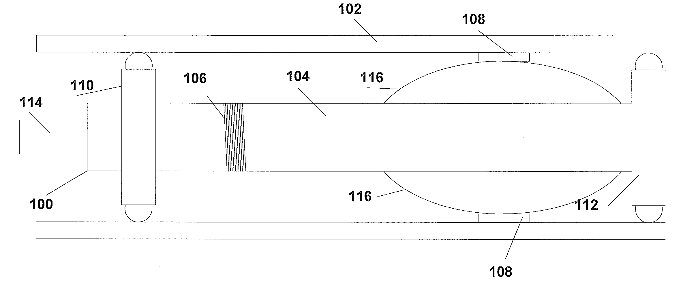
[0033]FIG. 1A illustrates an example of an eddy inner probe 100 according to some embodiments of the present invention. As shown in FIG. 1, a transmi...


PUM

PropertyMeasurementUnit
frequencyaaaaaaaaaa
diameteraaaaaaaaaa
lengthaaaaaaaaaa

Abstract

In accordance with aspects of the present invention, a method of inspecting a well tubular is disclosed. The method utilizes a probe with a transmitter and detectors spaced from the transmitter by at least twice the diameter of the pipe to be tested. In some cases where multi-tubular structures are tested, the probe can include further detectors spaced from the transmitter by at least twice the diameter of the outer pipes as well. The phase of signals detected by the detectors relative to the transmitter are utilized to detect faults in the pipes.

Description

RELATED APPLICATIONS[0001]The present application claims priority to U.S. Provisional Application 61 / 393,282, filed on Oct. 14, 2010, by Yarbro et al., entitled “Method for Measuring Remote Field Eddy Current Thickness in Multiple Tubular Configuration,” which is herein incorporated by reference in its entirety.TECHNICAL FIELD[0002]The present invention relates to measurement of thicknesses in tubular configurations utilizing remote field eddy currents and to remote field eddy current measurement in single or multiple tubular with magnetic permeability variations.DISCUSSION OF RELATED ART[0003]Aging oilfield tubular create environmental and economic risk to operators. Early identification and remediation is key to mitigating these hazards. Remote Field Eddy Current inspection techniques are commonly used to evaluate the thickness of down hole tubular and detect defects. The technique is viable in single tubular configurations. However, in multiple string configuration, the resultant...

Claims


Application Information

Patent Timeline
Patent Type & Authority Applications(United States)
IPC IPC(8): G01N27/90
CPCE21B47/082G01B7/10G01V3/12G01N33/20G01N27/9066E21B47/085
Inventor YARBRO, GREGORY SCOTTLI, JINGBITTAR, MICHAEL
Owner HALLIBURTON ENERGY SERVICES INC
Learn More