Controlled gate system with electromagnetic locking mechanism

a technology of electromagnetic locking mechanism and gate system, which is applied in the direction of burglar alarm by opening, building components, instruments, etc., and can solve problems such as theft or illegal exit from the establishmen

Inactive Publication Date: 2013-08-08
LES ATELIERS BOLDUC & FRERES
View PDF2 Cites 31 Cited by
  • Summary
  • Abstract
  • Description
  • Claims
  • Application Information

AI Technical Summary

Problems solved by technology

Accordingly, theft or illegal exit from the establishment occurs at the entry end where, for example, a person can jump the barrier gates or an adjacent fence with stolen goods.

Method used


Image

  • Controlled gate system with electromagnetic locking mechanism
  • Controlled gate system with electromagnetic locking mechanism
  • Controlled gate system with electromagnetic locking mechanism

Examples


Embodiment Construction

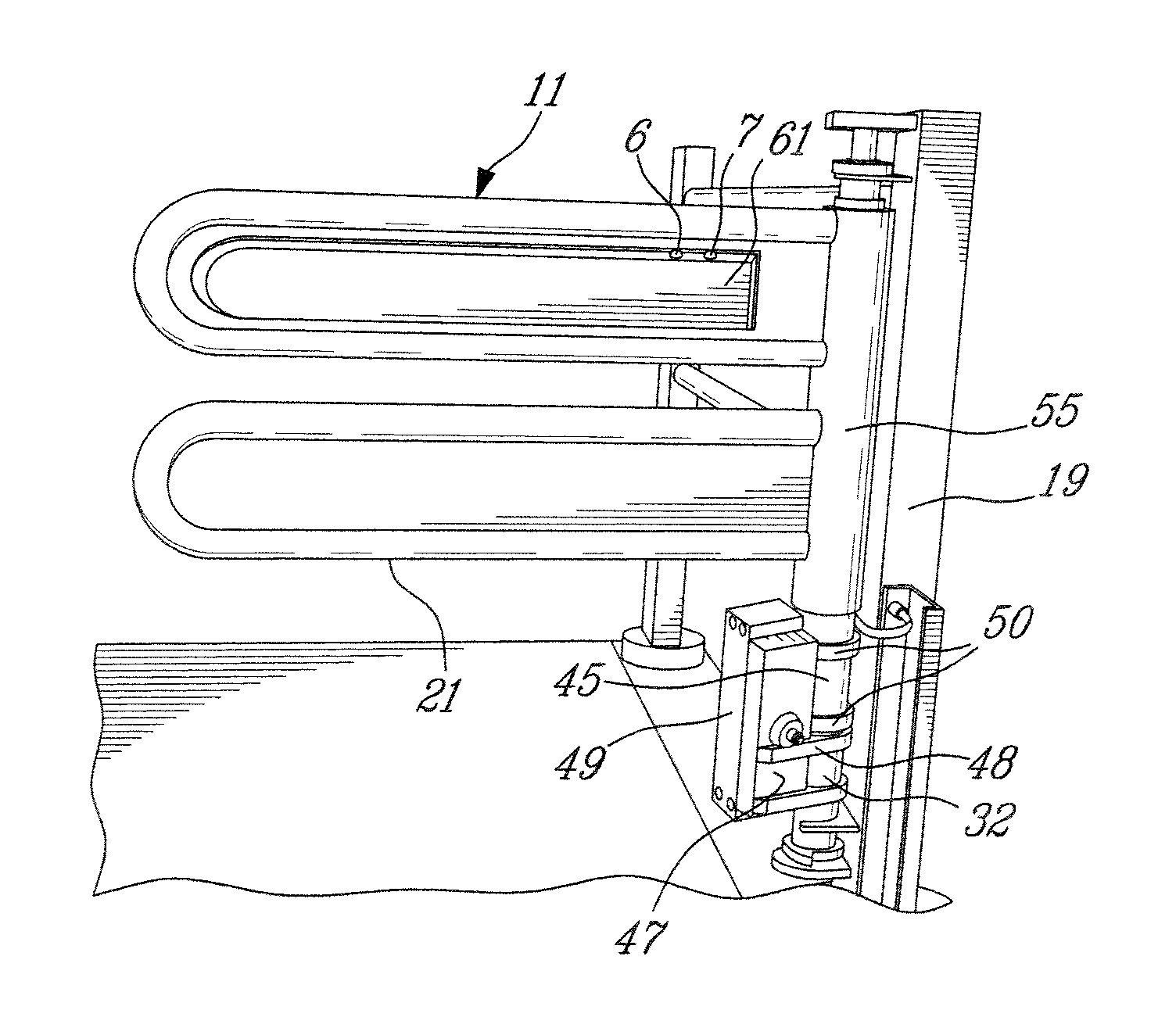
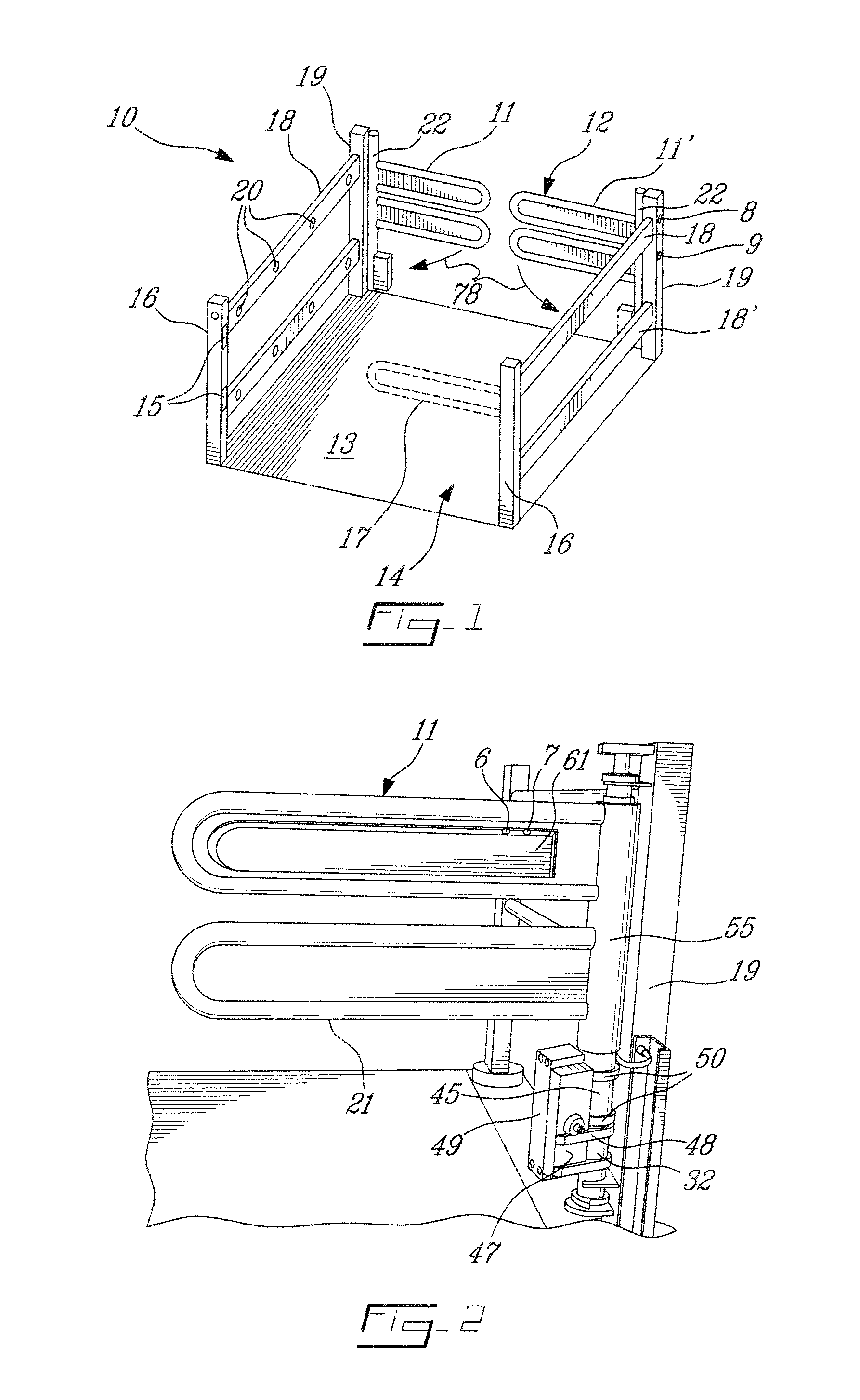
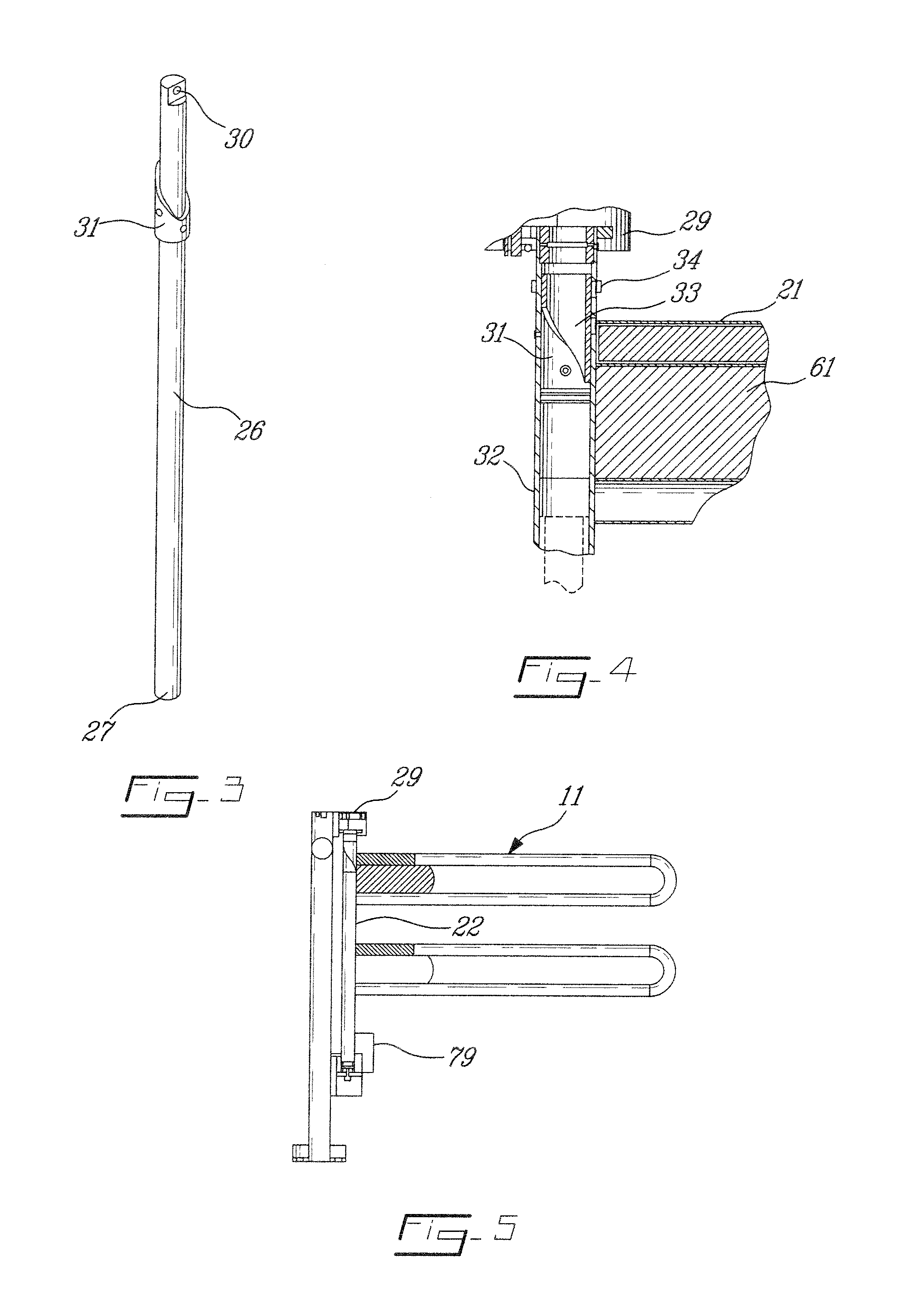
[0024]Referring now to the drawings and more particularly to FIG. 1, there is shown generally at 10 a controlled gate system constructed in accordance with the present invention. The controlled gate system as herein illustrated is comprised of two barrier gates 11 and 11′ secured in side-by-side alignment at an exit end 12 of a restricted passageway 13 defined between an entry end 14 and the exit end 12. The controlled gate system is installed in an establishment next to the entry doors thereof (not shown). Although the controlled gate system herein illustrated has two barrier gates 11 and 11′, it is contemplated that it may have a single gate 11 and operate in the same fashion as described herein.

[0025]Motion detectors are provided at the entry end 14 and may be comprised of electronic motion detectors 15 using logic to detect the presence of a person. The detector is disposed within vertical posts 16 at the entry end of the passageway. The motion detector may also consist of pivot...


PUM


Abstract

A controlled gate system for use in a restricted passage having an entry end and an exit end is described. The system comprises a barrier gate secured to a pivotal support assembly at the exit end to permit the barrier gate to pivot from a closed position, obstructing the restricted passage, to an open position, outwardly of the restricted passage to permit entry into an establishment. An electrically actuable brake, arrests the gate at the closed position and it is deactivated by a detector activated by a person at the entry end. An electromagnetic arresting mechanism is provided to disconnect the barrier gate from the electrically actuable brake to permit the barrier gate to swing freely within and out of the passage to provide for evacuation in emergency situations.

Description

TECHNICAL FIELD[0001]The present invention relates to a controlled gate system for use in a restricted passage having an entry end and an exit end with a barrier gate provided at the exit end and wherein mechanisms are provided to permit evacuation from inside an establishment through the restricted passage by automatically disconnecting the barrier gate causing it to swing freely.BACKGROUND ART[0002]Reference is made to our related U.S. patent application Ser. No. 12 / 471,440, filed on May 25, 2009, and entitled “Gate System With Automatic Locking And Unlocking Feature”, which describes a controlled gate system with automatic locking and unlocking features. These controlled gate systems with restricted passage are installed at the entry doors of an establishment and in many cases, are located far from the exit doors where the checkout counters and registries are located. It is at the exit end of an establishment, such as grocery and other merchandising shopping establishments where ...

Claims


Application Information

Patent Timeline
Patent Type & Authority Applications(United States)
IPC IPC(8): E05F15/20E05B47/02G08B13/08E06B3/36
CPCG08B13/08E05B47/023E05B65/0007E06B11/085E05F15/72E05Y2201/462E05Y2800/416E05Y2800/254E05G5/003
Inventor LACHANCE, JEROMEMERCIER, YVANBOLDUC, RENE
Owner LES ATELIERS BOLDUC & FRERES
Why Eureka
Try Eureka