Forward converter with magnetic component

a forward converter and magnetic component technology, applied in the direction of magnetic bodies, instruments, process and machine control, etc., can solve the problems of limiting undesired losses, restricting power density and efficiency, etc., to minimize overall thermal resistance, reduce leakage, and minimize copper power and inductance losses

Active Publication Date: 2013-08-08
DELTA ELECTRONICS (THAILAND) PUBLIC CO LTD
View PDF10 Cites 21 Cited by
  • Summary
  • Abstract
  • Description
  • Claims
  • Application Information

AI Technical Summary

Benefits of technology

[0008]It is the object of the invention to create a forward converter comprising a magnetic component pertaining to the technical field initially mentioned, that enables flexible assembly, while providing lower leakage, minimized copper power and inductance losses, as well as minimized overall thermal resistance.

Problems solved by technology

While the transformer core is optimally used due to symmetrical excitation in two quadrants of the B-H plane, the output ripple is relatively large and a large output filtering inductor is required, which restricts the power density and efficiency.
Large transformer and output filtering inductors are required, which limits the power density and efficiency.
Winding bobbins lead to undesired losses, whereas disposing legs opposing each other requires complicated assembly steps.
These cores are not flexible in term of mounting and of adjusting the magnetizing and filtering inductance through air gap.
A single air gap is manufactured on the centre leg of an E / ER core by machine and bobbins are unavoidable to wind the coils.
The single air gap, the winding bobbin, and the inflexible assembly affect negatively the costs, the power density, the power efficiency, and the thermal distribution.
The winding bobbins and single air gap lead to high costs and cause more leakage as well as inductance losses.

Method used


Image

  • Forward converter with magnetic component
  • Forward converter with magnetic component
  • Forward converter with magnetic component

Examples


Embodiment Construction

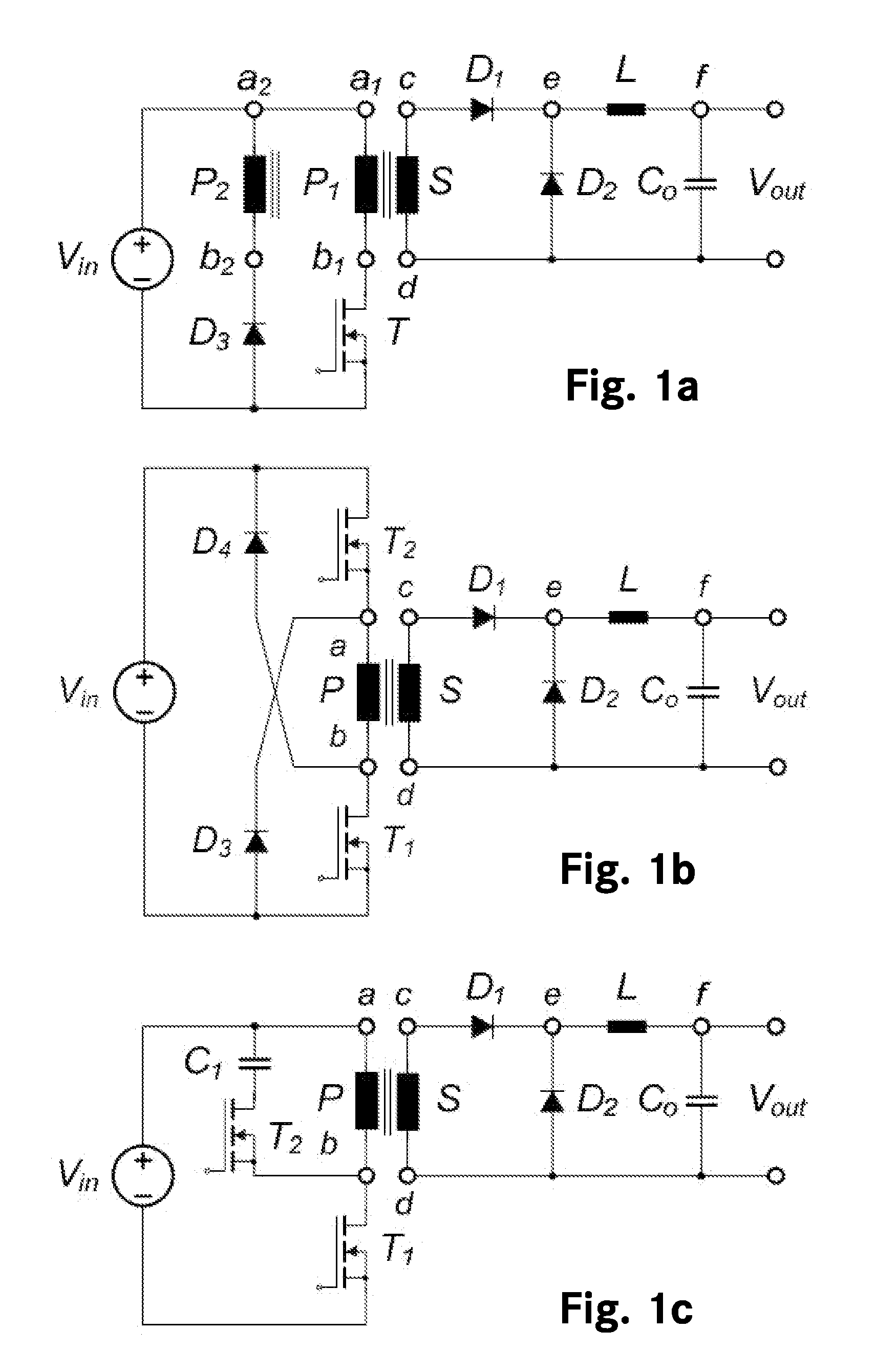
[0033]FIG. 1a shows a prior art single transistor forward converter, which has a three winding transformer with a first primary winding P1, a second primary winding P2, and a secondary winding S. An input source Vin is connected through transistor T to the first primary winding P1 and through diode D3 to the second primary winding P2. The secondary winding S is connected through diode D1 to diode D2, and further connected to filter output inductor L and capacitor Co in order to provide the output voltage Vout.

[0034]FIG. 1b shows a prior art two-transistor forward converter, which has a two winding transformer with a primary winding P and a secondary winding S. An input source Vin is connected through two diodes D3, D4 and two transistors T1, T2 to the primary winding P. The secondary winding S is connected through diode D1 to diode D2, and further connected to filter output inductor L and capacitor Co in order to provide the output voltage Vout.

[0035]FIG. 1c shows a prior art active...


PUM

PropertyMeasurementUnit
stray inductanceaaaaaaaaaa
permeabilityaaaaaaaaaa
saturation flux densityaaaaaaaaaa

Abstract

A forward converter comprises a magnetic component with a transformer and a filter output inductor. Also disclosed is a method for assembly of a forward converter. A first and a second U/UR core are arranged to form an O-core. Windings of the transformer are arranged on the O-core. A bobbin-less U/UR core is arranged to abut the O-core, and windings of a filter output inductor are arranged directly on a body section of the bobbin-less U/UR core. Alternatively, windings of the transformer are arranged on a first section of an E/ER core, and windings of the filter output inductor are arranged directly on a second, bobbin-less section of the E/ER core.

Description

TECHNICAL FIELD[0001]The invention relates to a forward converter comprising a magnetic component with a transformer and a filter output inductor, and to method steps in the assembly of a forward converter comprising a magnetic component with a transformer and a filter output inductor.BACKGROUND ART[0002]In power converters with integrated magnetic components and converters with analogous magnetic components, E / ER cores are provided. The term “E / ER core” should be understood as “E core and / or ER core”. Windings of a transformer and a filter output inductor are arranged on winding bobbins, which are further arranged on legs of the E / ER core. Switched mode power converters and specifically DC / DC power converters are widely used in telecommunication and commercial systems, for example, and improvements in this field of technology are of high importance, in particular improvements with respect to power density, reduced costs, lowered losses, and / or improved efficiency as well as thermal...

Claims


Application Information

Patent Timeline
Patent Type & Authority Applications(United States)
IPC IPC(8): H02M3/335H02M1/00
CPCH02M3/335H01F3/10H01F27/306H01F27/38Y10T29/49073H01F41/02H02M3/33553H02M2001/0064H01F38/40H02M1/0064
Inventor NJIENDE, T. HUGUES DOUGLASHELDT, DIETER
Owner DELTA ELECTRONICS (THAILAND) PUBLIC CO LTD
Why Eureka
Try Eureka