Unlock instant, AI-driven research and patent intelligence for your innovation.

Cleaner-head for a vacuum cleaner

Inactive Publication Date: 2013-08-15
DYSON TECH LTD
View PDF5 Cites 15 Cited by
  • Summary
  • Abstract
  • Description
  • Claims
  • Application Information

AI Technical Summary

Benefits of technology

The present invention provides a cleaner head with a simplified cooling system. The brush bar is no longer used as an air duct, so there is no need for a dynamic seal to isolate clean air from dirty air. Instead, separate dedicated ducts are provided to supply and exhaust the cooling air. This greatly simplifies the cooling system and reduces material costs without the risk of motor damage. The motor is located inside the brush bar and is cantilevered through one end of the brush bar. The stationary ducts are preferably arranged in a simple and compact configuration, either by connecting to air intakes and exhausts through the first end of the brush bar or by providing cooling holes on the motor section outside the brush bar. The clean air inlet may be provided at the first end of the cleaner head to reduce the length of the stationary ducts. The brush bar can be easily removed for cleaning, repair or replacement without the need for inhibiting the motor support assembly or stationary duct(s).

Problems solved by technology

In the arrangement described in U.S. Pat. No. 6,323,570, because the brush bar functions as an air duct, upstream of the motor, a puncture in the brush bar wall introduces a risk of dirty air in the main suction chamber being sucked through the brush bar and into the motor, with possible damage to the motor.

Method used


Image

  • Cleaner-head for a vacuum cleaner
  • Cleaner-head for a vacuum cleaner
  • Cleaner-head for a vacuum cleaner

Examples


Embodiment Construction

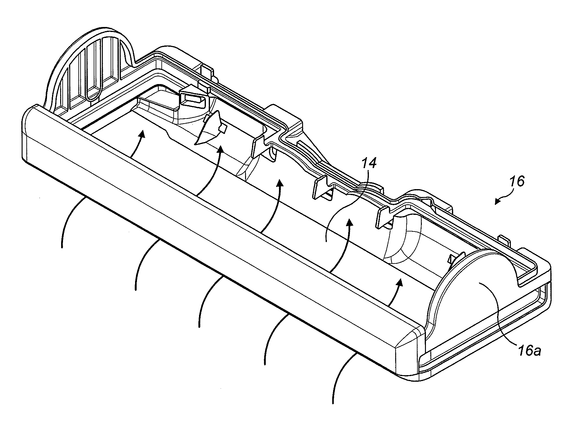
[0033]FIG. 1 shows an upright vacuum cleaner 2. The cleaner 2 has a rolling head assembly 4 which carries a fixed cleaner head 6, and an ‘upright’ body 8 which can be reclined relative to the head assembly 4 and which includes a handle 10 for manouevring the cleaner 2 across the floor. In use, a user grasps the handle 10 and reclines the upright body 8 until the handle 10 is disposed at a convenient height for the user; the user can then roll the vacuum cleaner 2 across the floor using the handle 10 in order to pick up dust and other debris on the floor.

[0034]The vacuum cleaner 2 picks up the dirt and debris by entraining it in a “dirty” airflow, which is sucked in through the cleaner head 6 by a vac-motor onboard the cleaner 2.

[0035]This dirty airflow is then ducted—under the suction pressure generated by the vac-motor—to a cyclonic separating apparatus 12, where dirt is separated from the air before the relatively clean air is then exhausted back to the atmosphere.

[0036]The dirty ...


PUM


Abstract

A cleaner head for a vacuum cleaner has a rotating brush bar driven by an air-cooled motor, which is mounted inside the cleaner head with at least a section of the motor being located inside the brush bar. To cool the motor in use, an external casing of the motor is provided a plurality of air-cooling holes comprising at least one air intake and at least one air exhaust. These cooling holes are connected—intake to exhaust—to form one or more air-cooling paths through the inside of the motor. Each air intake is connected to an upstream clean air inlet by a stationary—not rotating—intake duct, and each air exhaust is similarly connected to a downstream clean air outlet by a stationary—not rotating—exhaust duct. This avoids the problems associated with using the rotating brush bar itself as a duct for carrying cooling air to the motor.

Description

REFERENCE TO RELATED APPLICATIONS[0001]This application claims the priority of United Kingdom Application No. 1202177.0 filed on Feb. 8, 2012, the entire contents of which are incorporated herein by reference.FIELD OF THE INVENTION[0002]The present invention relates to the field of vacuum cleaners, and in particular to a cleaner head for a vacuum cleaner.[0003]The invention is concerned specifically with cleaner heads which incorporate a motor-driven agitator. The vacuum cleaner, on the other hand, may be of any general type. For example, the cleaner head may be a fixed cleaner head on an upright vacuum cleaner, or alternatively it may be the cleaner head of a floor tool used with a cylinder vacuum cleaner or stick-vac cleaner. The invention is not limited to cyclonic vacuum cleaners.BACKGROUND OF THE INVENTION[0004]It is conventional to provide the cleaner head of a vacuum cleaner with an agitator, such as a rotating brush bar, for agitating or “beating” a floor surface—particularl...

Claims


Application Information

Patent Timeline
IPC IPC(8): A47L9/04
CPCA47L9/0411A47L9/0438H02K7/14A47L9/0477A47L9/2889A47L9/0455
Inventor DYSON, JAMESLESNIOWSKI, CHRISTOPHERCOURTNEY, STEPHEN BENJAMIN
Owner DYSON TECH LTD