

Optical scanning device and image display apparatus
- Summary
- Abstract
- Description
- Claims
- Application Information
AI Technical Summary
Benefits of technology
Problems solved by technology
Method used
Image

Examples
1st embodiment
(1) 1st Embodiment
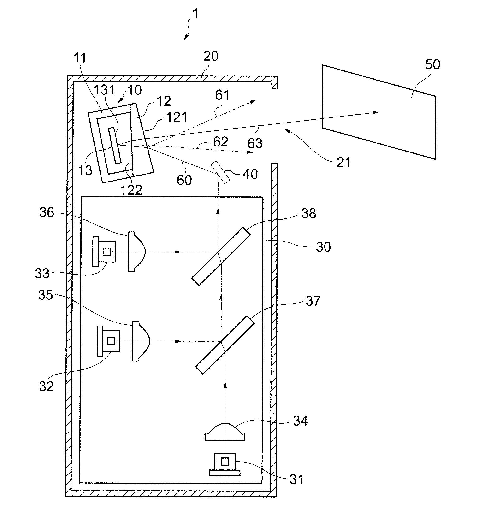
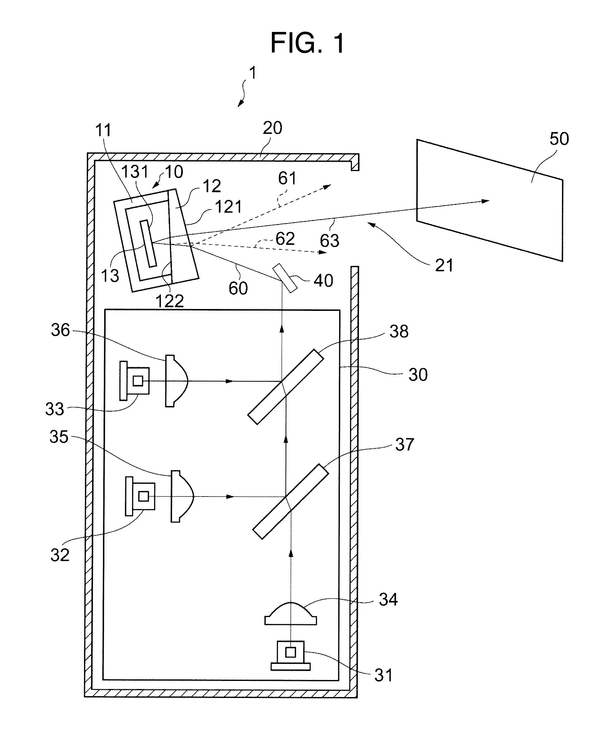
[0029]In FIG. 1, a reference numeral 1 denotes, as a whole, an image display apparatus including an optical scanning unit 10 according to a first embodiment of the present invention. The image display apparatus 1 is constituted by including a light-source unit 30, a reflection minor 40, and the optical scanning unit 10 inside an image display apparatus' housing (which, hereinafter, will be referred to as “display-apparatus housing”) 20. This display-apparatus housing 20 forms an outer frame of the image display apparatus, and is equipped with an aperture portion 21. Here, a light beam that is scanned by the optical scanning unit 10 onto a screen 50 or the like is so guided as to pass through this aperture portion 21.
[0030]First, the explanation will be given below concerning the light-source unit 30. The light-source unit 30 includes a first laser light-source 31, a second laser light-source 32, a third laser light-source 33, a first collimator lens 34, a second co...
2nd embodiment
(2) 2nd Embodiment
[0080]FIG. 7 illustrates a configuration example of the optical scanning unit 70 according to the second embodiment. Excluding a light-transmissive cover 72, configuration components of the optical scanning unit 70 are the same as those of the optical scanning unit 10. Accordingly, the explanation thereof will be omitted here.
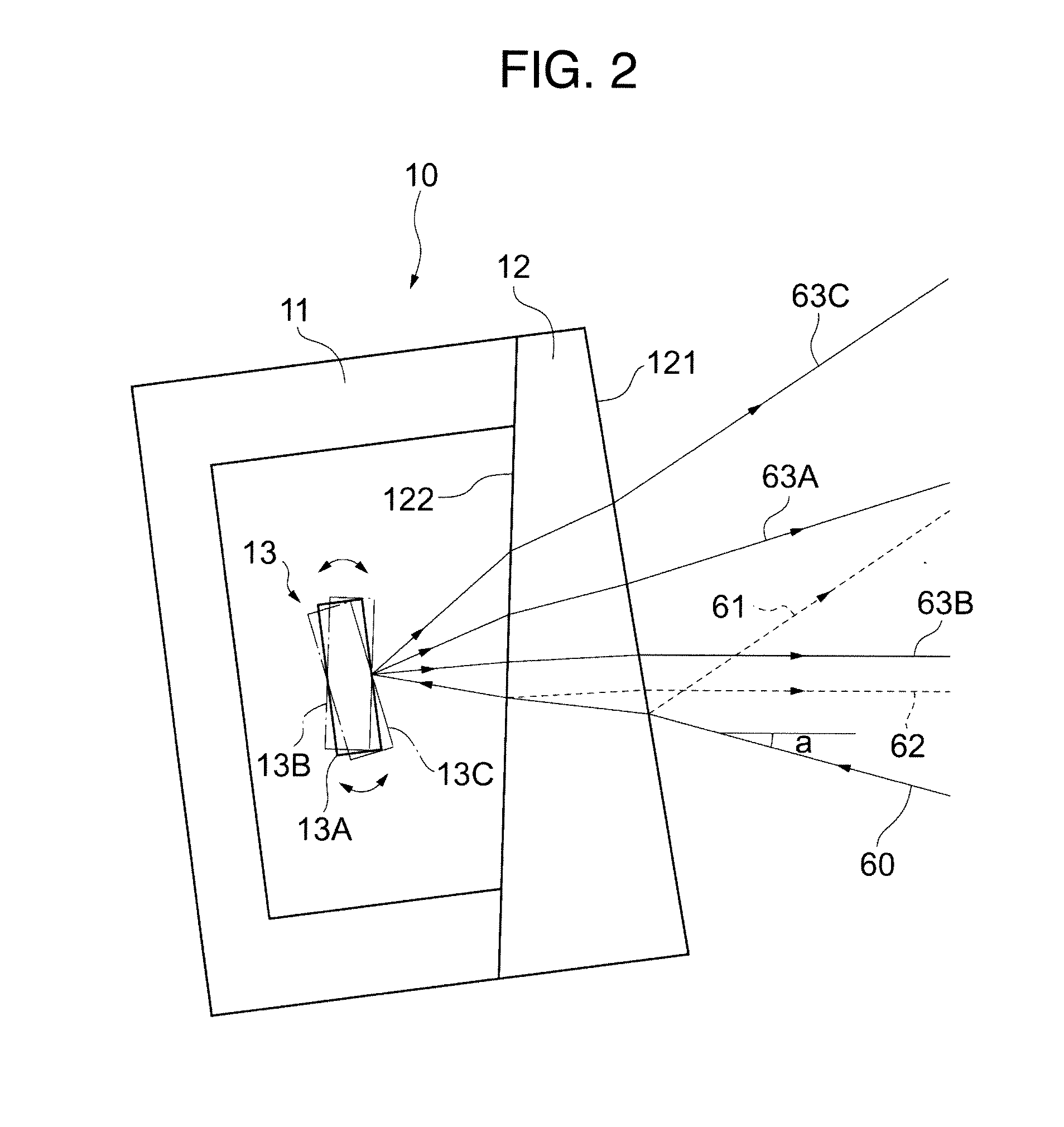
[0081]As is the case with the light-transmissive cover 12 in the first embodiment, the light-transmissive cover 72 is so provided as to be deployed as follows: Namely, an external plane 721 and an internal plane 722 of the light-transmissive cover 72 are made non-parallel to each other. In addition, the external plane 721 and the internal plane 722 are also made non-parallel to the reflection plane 131 of the rotationally-moving minor 13. Furthermore, the inclinations of the external plane 721 and the internal plane 722 of the light-transmissive cover 72 are determined so that the first reflected light 61 and the second reflected light 62 reac...
embodiment
(3) 3rd Embodiment
[0095]FIG. 9 illustrates a configuration example of the image display apparatus 2 according to the third embodiment. The configuration of the image display apparatus 2 is basically the same as that of the image display apparatus 1 illustrated in FIG. 1. Accordingly, the explanation thereof will be omitted here. Incidentally, the light-source unit 30, the reflection mirror 40, and the screen 50 illustrated in FIG. 1 are omitted in FIG. 9.
[0096]The aperture portion 21 is provided in the display-apparatus housing 20. Here, a light beam that is scanned by the optical scanning unit 10 onto the screen 50 or the like is so guided as to pass through this aperture portion 21. Moreover, a light-interrupting portion 22 is a partial portion of the display-apparatus housing 20. This light-interrupting portion 22 is positioned at a location at which, in the surroundings of the aperture portion 21, the optical paths of the first reflected light 61 and the second reflected light 6...
PUM
 Abstract
Description
Claims
Application Information