
Garment Dyeing Machine

Active Publication Date: 2013-08-29
CLOVER MYSTIQUE CO LTD
View PDF4 Cites 2 Cited by
  • Summary
  • Abstract
  • Description
  • Claims
  • Application Information

AI Technical Summary

Benefits of technology

The present invention is a garment dyeing machine that includes a container, a roller, and a nozzle. Garment pieces can be attached to the roller and sprayed with dye solution. The roller is inside the container and rotates around its central axis. This machine allows for easy and efficient dyeing of garments.

Problems solved by technology

In existing garment dyeing machines, a large quantity of water is required for dyeing garments, in particular brassieres.
Such is environmentally very unfriendly, and limits the development of garment dyeing industry in places with no abundant water supply.

Method used


Image

  • Garment Dyeing Machine
  • Garment Dyeing Machine
  • Garment Dyeing Machine

Examples


Embodiment Construction

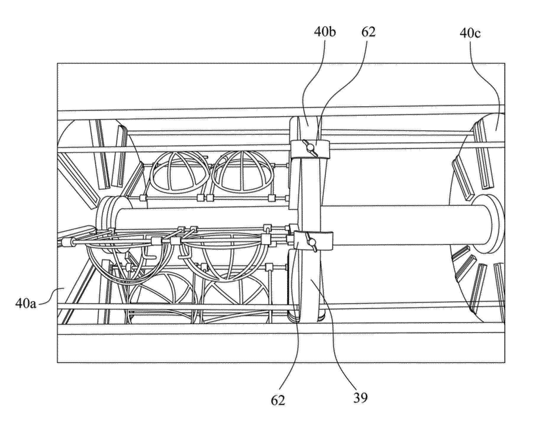
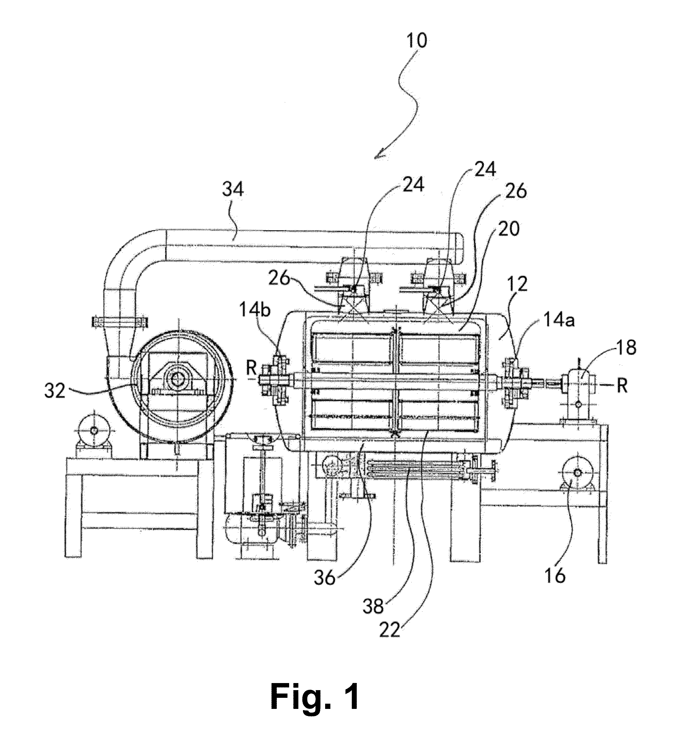
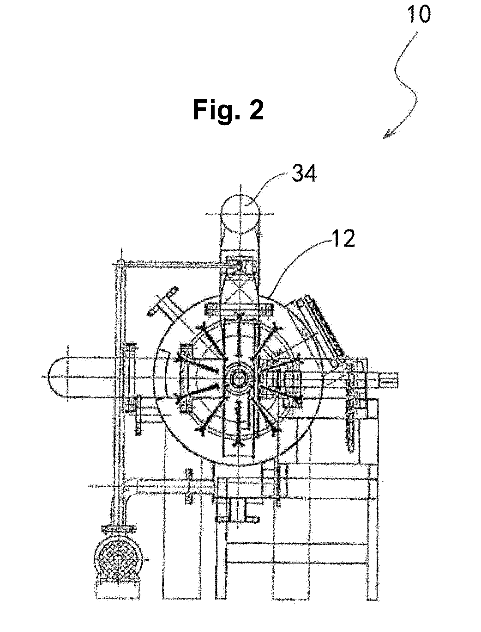
[0023]A garment dyeing machine according to an embodiment of the present invention is shown in FIGS. 1 to 3, and generally designated as 10. The machine 10 is suitable (but not limited) for dyeing such garments as lingerie and brassieres. The machine 10 includes a generally cylindrical container 12 with a pair of couplings 14a, 14b. A power motor 16 is associated with a power transmitter 18, which is connected with the coupling 14a. Upon operation of the power motor 16, the power transmitter 18 is activated to cause the coupling 14a to rotate about a horizontal axis of rotation R-R.

[0024]The container 12 has a cylindrical interior cavity 20 in which a roller 22 is installed. The roller 22 is engaged at one longitudinal end with the coupling 14a and at another longitudinal end with the coupling 14b such that rotation of the coupling 14a about the axis R-R will bring about simultaneous rotational movement of the roller 22 about the same axis R-R. The speed of rotation of the roller 22...


PUM


Abstract

A garment dyeing machine (10) includes a container (12), a roller (22) to which brassieres are releasably attachable, the roller (22) being within the container (12) and rotatable relative to the container (12) about an axis of rotation (R-R), the garment dyeing machine having two nozzles (24) for spraying a dye solution onto the roller (22).

Description

CROSS REFERENCE TO RELATED APPLICATIONS[0001]This application claims priority in U.S. Provisional Patent application Ser. No. 61 / 604,010, filed 28 Feb. 2012, the content of which is hereby incorporated by reference.FIELD OF THE INVENTION[0002]This invention relates to a garment dyeing machine, in particular a dyeing machine which is suitable (but not limited) for dyeing such garments as lingerie and brassieres.BACKGROUND OF THE INVENTION[0003]In existing garment dyeing machines, a large quantity of water is required for dyeing garments, in particular brassieres. In particular, in conventional dyeing operations, the fabric to dye solution ratio by weight is roughly 1:4. Such is environmentally very unfriendly, and limits the development of garment dyeing industry in places with no abundant water supply.[0004]It is thus an object of the present invention to provide a garment dyeing machine in which the aforesaid shortcomings are mitigated, or at least to provide a useful alternative t...

Claims


Application Information

Patent Timeline
IPC IPC(8): D06B23/04D06B1/08D06B23/00
CPCD06B5/24D06B23/14D06B23/04D06B19/0088D06B1/02Y02P70/62
Inventor LEE, SZE NGOKCHANG, KUAN YAU NANCY
Owner CLOVER MYSTIQUE CO LTD
Learn More