Terminal and method for charging battery of sub terminal connected to main terminal

Inactive Publication Date: 2013-08-29
PANTECH CO LTD
View PDF0 Cites 2 Cited by
  • Summary
  • Abstract
  • Description
  • Claims
  • Application Information

AI Technical Summary

Benefits of technology

This patent describes an apparatus and method for charging a main terminal and sub terminal using a single charger. When the main terminal charges the sub terminal, the control unit maintains the first charging current for the main terminal and uses a second charging current for the sub terminal. The control unit also provides the charging current to the sub terminal if the remaining battery power of the first battery is greater than a threshold battery power. This invention allows for efficient charging of multiple devices using a single charger.

Problems solved by technology

However, if the two chargers are separately provided with the portable electronic device, the configuration of the portable electronic device may be complicated and less efficient since two separate charger connectors and charging circuits are provided.
Furthermore, since two outlets are occupied for the respective chargers, it may be inconvenient to charge the two terminals when the user is on the move or when there are insufficient outlets available.

Method used


Image

  • Terminal and method for charging battery of sub terminal connected to main terminal
  • Terminal and method for charging battery of sub terminal connected to main terminal
  • Terminal and method for charging battery of sub terminal connected to main terminal

Examples


Embodiment Construction

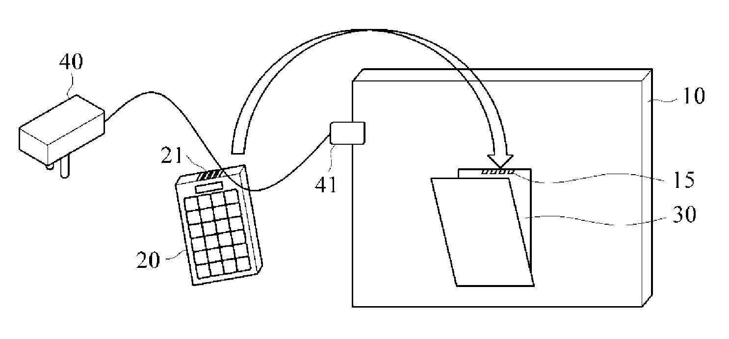
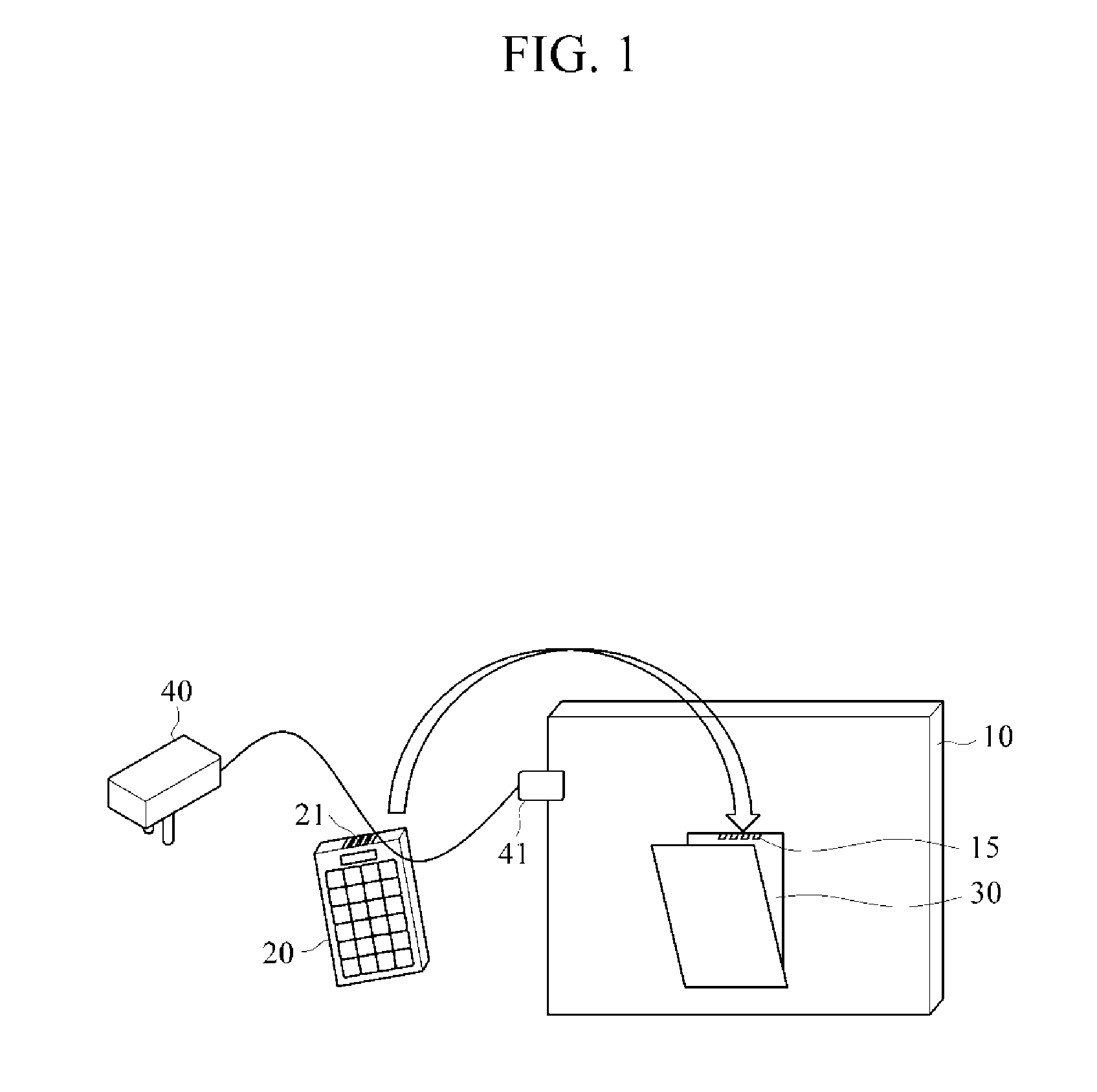
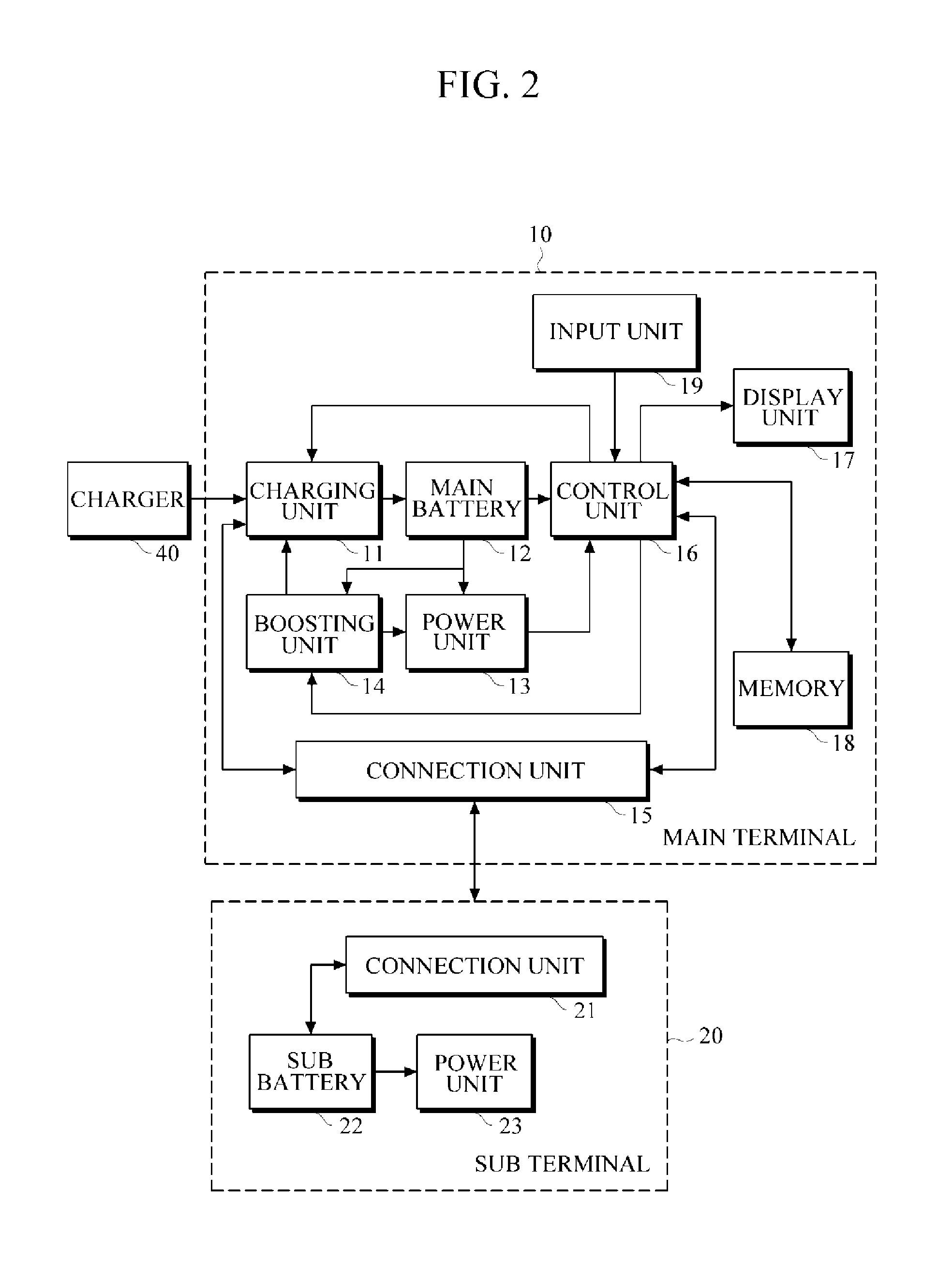
[0022]The invention is described more fully hereinafter with reference to the accompanying drawings, in which exemplary embodiments of the invention are shown. This invention may, however, be embodied in many different forms and should not be construed as limited to the exemplary embodiments set forth herein. Rather, these exemplary embodiments are provided so that this disclosure is thorough, and will fully convey the scope of the invention to those skilled in the art. It will be understood that for the purposes of this disclosure, “at least one of X, Y, and Z” can be construed as X only, Y only, Z only, or any combination of two or more items X, Y, and Z (e.g., XYZ, XZ, XYY, YZ, ZZ). Throughout the drawings and the detailed description, unless otherwise described, the same drawing reference numerals are understood to refer to the same elements, features, and structures. The relative size and depiction of these elements may be exaggerated for clarity.

[0023]According to aspects of t...


PUM


Abstract

A main terminal including a connection unit connectable to a subordinate terminal, a charging unit to charge a first battery of the main terminal and to charge a second battery of the subordinate terminal, and a control unit to maintain a first charging current to the main terminal regardless of whether a second charging current is provided to the subordinate terminal. A method for controlling a charging current for a subordinate terminal connected to a main terminal including recognizing a voltage of a battery of the subordinate terminal, determining a charging current for the battery of the subordinate terminal, and providing the charging current to the battery if the voltage of the battery is less than or equal to a target voltage.

Description

CROSS-REFERENCE TO RELATED APPLICATION[0001]This application claims priority from and the benefit under 35 U.S.C. §119(a) of Korean Patent Application No. 10-2012-0021453, filed on Feb. 29, 2012, which is incorporated herein by reference for all purposes.BACKGROUND[0002]1. Field[0003]The following description relates to a battery charging apparatus and method, and more particularly, to an apparatus and method for charging a battery of a sub terminal connected to a main terminal.[0004]2. Discussion of the Background[0005]Portable electronic devices have become necessities of modern life and continuous technical development has enabled them to be smaller, lighter, and capable of providing various functions, e.g., music player for MP3 file format, camera, navigation, etc. A portable electronic device receives power supplied from a secondary battery, such as a lithium ion battery or lithium polymer battery. Hence, before the battery is fully discharged, the portable electronic device ma...

Claims


Application Information

Patent Timeline
IPC IPC(8): H02J7/00
CPCH02J7/007H02J7/0022H02J7/0021H02J7/0044H02J7/0013H02J7/0049Y02E60/10H02J7/04H01M10/46
Inventor KANG, SE-GU
Owner PANTECH CO LTD
Why Eureka
Try Eureka