Clip applier

a technology of applier and clip, which is applied in the field of medical operations system, can solve the problem that the clip is generally unsuitable for clamping the vessel, and achieve the effect of improving the clamping

Inactive Publication Date: 2013-08-29
BOSTON SCI SCIMED INC
View PDF11 Cites 110 Cited by
  • Summary
  • Abstract
  • Description
  • Claims
  • Application Information

AI Technical Summary

Problems solved by technology

Although clipping devices have been employed in controlling internal bleeding (e.g., from surgical wounds or n...

Method used


Image

  • Clip applier
  • Clip applier
  • Clip applier

Examples


Embodiment Construction

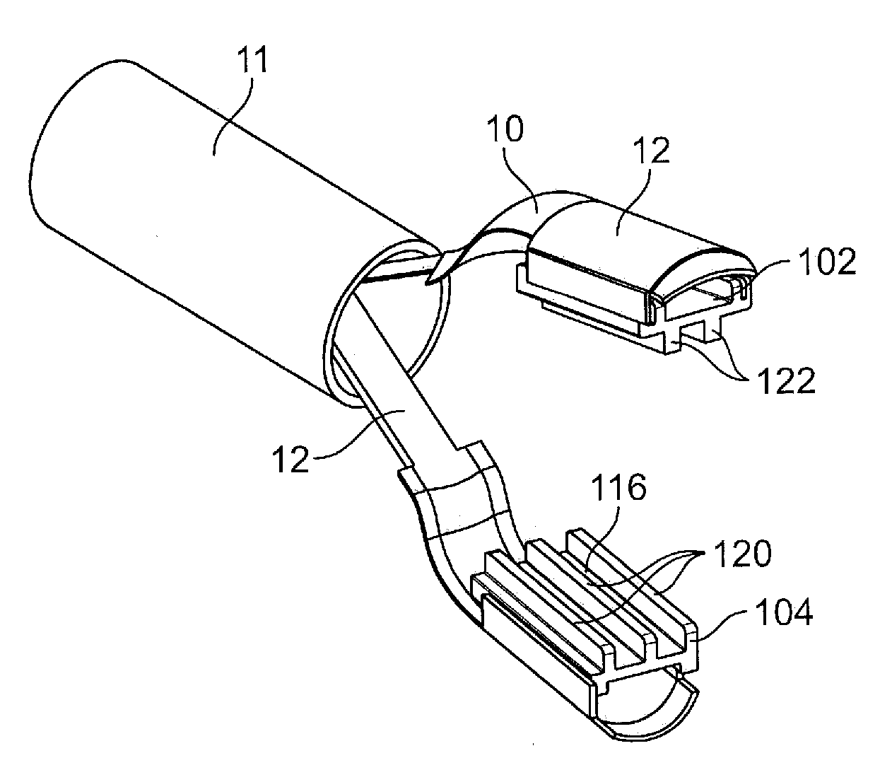
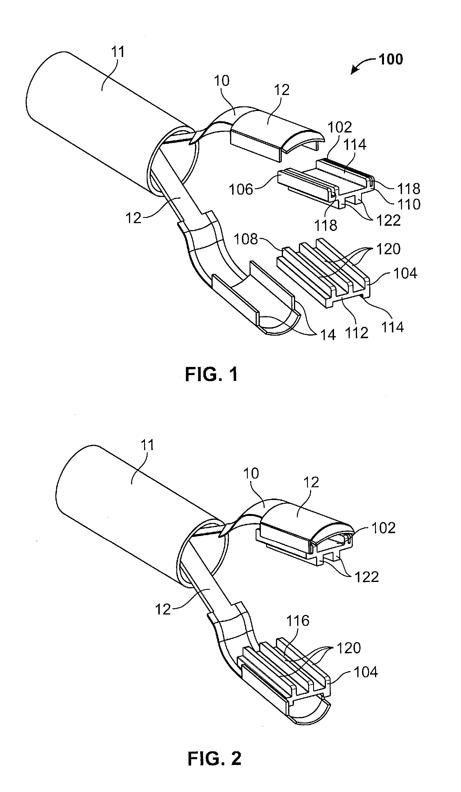
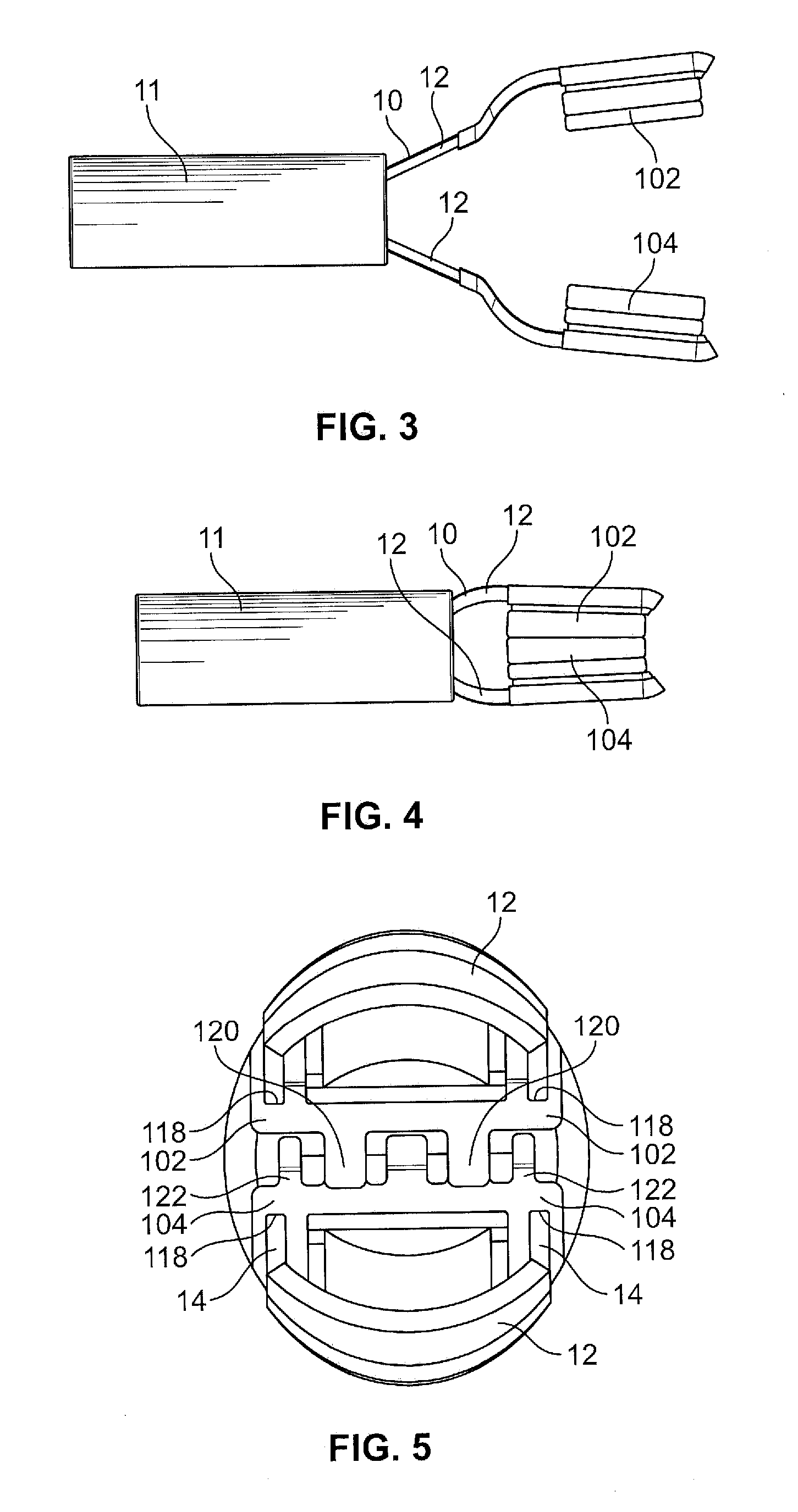
[0025]The present invention may be further understood with reference to the following description and the appended drawings, wherein like elements are referred to with like reference numerals. The present invention relates to a clip for use in sealing lumens of body vessels and / or to an adaptor plate configured for placement over arms of a known hemostasis clip to configure the clip for use in sealing a body lumen, vessel, duct or organ. The clips according to the invention are configured to apply a substantially constant constrictive pressure over a target portion of tissue while minimizing trauma thereto to substantially seal a vessel within the tissue. In an exemplary embodiment, the adaptor plates are configured so that, when added to an existing hemostatic clip, a surface area over which arms of the clip contact tissue is expanded to spread a force drawing the clip arms closed over a wider surface area of tissue—e.g., to prevent fluid flow through a target vessel, as will be de...


PUM


Abstract

A system for performing a medical operation includes an end effector having first and second arms, each extending from a distal end to a proximal end, the proximal ends being connected to one another, the end effector being movable between a closed configuration wherein the first and second arms are separated from one another by a first distance and an open configuration wherein the first and second arms are separated from one another by a second distance greater than the first distance, a distance between the first and second arms being substantially constant from the proximal ends to the distal ends, wherein the end effector is biased to the open configuration. A first plate element extends from a first surface configured to engage a first wall of the first arm to a second surface configured to contact target tissue in an operative configuration. A second plate element extends from a first surface configured to engage a first wall of the second jaw to a second surface configured to contact target tissue in an operative configuration.

Description

PRIORITY CLAIM[0001]This present application claims the priority to the U.S. Provisional Application Ser. No. 61 / 604,012, entitled “Clip Applier” filed on Feb. 28, 2012. The specification of the above-identified application is incorporated herewith by reference.BACKGROUND[0002]Surgical procedures often require the clamping of vessels to prevent the flow of fluids therethrough. Although clipping devices have been employed in controlling internal bleeding (e.g., from surgical wounds or naturally occurring damage) these clips are generally unsuitable to clamp vessels to prevent fluid flow therethrough.SUMMARY OF THE INVENTION[0003]The present invention relates to a system for performing a medical operation which includes an end effector having first and second arms, each extending from a distal end to a proximal end, the proximal ends at the arms being connected to one another, the end effector being movable between a closed configuration wherein the first and second arms are separated...

Claims


Application Information

Patent Timeline
IPC IPC(8): A61B17/128A61B17/122
CPCA61B17/122A61B17/128A61B2017/12004A61B2017/2825A61B17/1285A61B2017/00862A61B2017/00477
Inventor KAPPEL, GARYSMITH, PAULWEITZNER, BARRY
Owner BOSTON SCI SCIMED INC
Why Eureka
Try Eureka