Surgical staple cartridge with enhanced knife clearance

Active Publication Date: 2014-07-03
INTUITIVE SURGICAL OPERATIONS INC
View PDF13 Cites 245 Cited by
  • Summary
  • Abstract
  • Description
  • Claims
  • Application Information

AI Technical Summary

Benefits of technology

[0012]Improved surgical clamping and cutting instruments (e.g., surgical staplers, and electrosurgical vessel sealing devices) and related methods are disclosed. Surgical clamping and cutting instruments described herein employ a proximal to distal knife movement, thereby orienting the knife to greatly reduce the likelihood of unintentionally cutting tissue while removing the surgical instrument from the surgical site in the event that the surgical instrument fails to fully actuate. Surgical clamping and cutting instruments described herein locate the knife and associated drive mechanism distal to the wrist of the

Problems solved by technology

Known surgical clamping and cutting instruments, however, may fail to be both compact and maneuverable.
For example, known surgical staplers may lack maneuverability with respect to multiple degrees of freedom (e.g., Roll, Pitch, and Yaw) and associated desired ranges of motion.
Additional

Method used


Image

  • Surgical staple cartridge with enhanced knife clearance
  • Surgical staple cartridge with enhanced knife clearance
  • Surgical staple cartridge with enhanced knife clearance

Examples


Embodiment Construction

[0066]In the following description, various embodiments of the present invention will be described. For purposes of explanation, specific configurations and details are set forth in order to provide a thorough understanding of the embodiments. However, it will also be apparent to one skilled in the art that the present invention may be practiced without the specific details. Furthermore, well-known features may be omitted or simplified in order not to obscure the embodiment being described.

[0067]Minimally Invasive Robotic Surgery

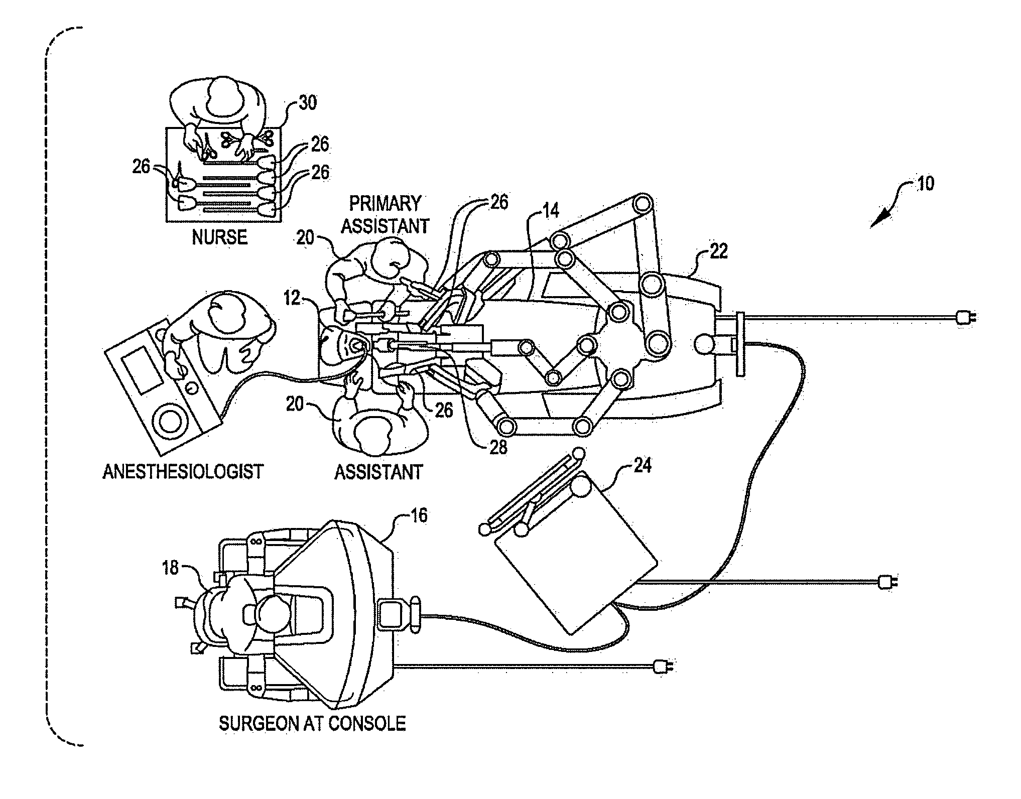
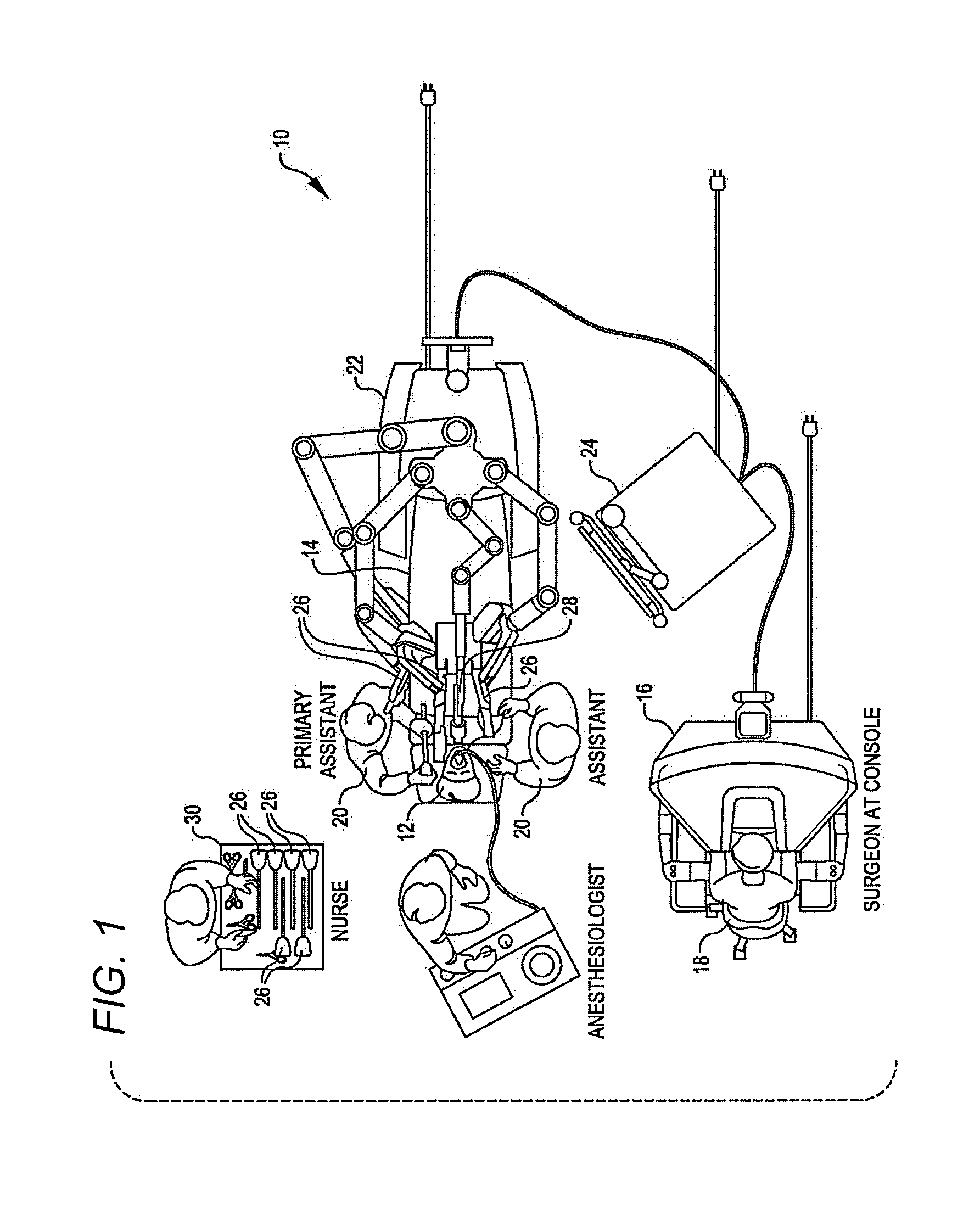
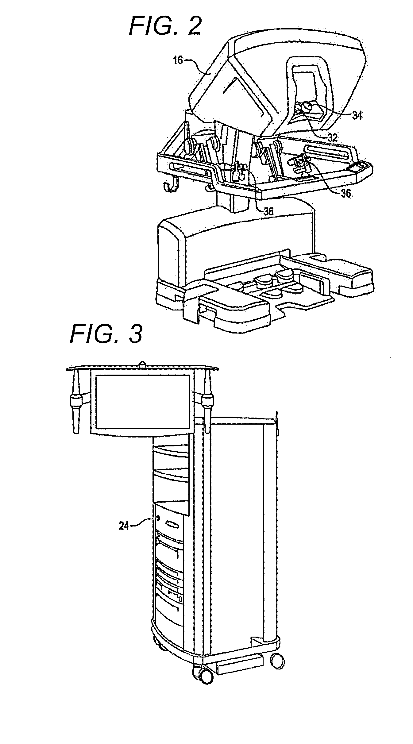
[0068]Referring now to the drawings, in which like reference numerals represent like parts throughout the several views, FIG. 1 is a plan view illustration of a Minimally Invasive Robotic Surgical (MIRS) system 10, typically used for performing a minimally invasive diagnostic or surgical procedure on a Patient 12 who is lying down on an Operating table 14. The system can include a Surgeon's Console 16 for use by a Surgeon 18 during the procedure. One or more...


PUM

PropertyMeasurementUnit
Lengthaaaaaaaaaa
Angleaaaaaaaaaa
Angleaaaaaaaaaa

Abstract

A surgical instrument having an elongated shaft having a shaft distal end and a shaft proximal end. An end effector is coupled to the shaft distal end and includes opposed jaws. A housing is included in one of the jaws, the housing having a housing proximal end, a housing distal end, an upper surface, a distal garage having lateral surfaces that extend above the upper surface, and a plurality of staple openings extending through the upper surface. A knife member is supported within the housing for movement distally. The knife member is moveable into a predetermined parked position such that a first portion of the cutting blade displaces below the upper surface and a second portion remains displaced above the upper surface. There is enough lateral clearance in the predetermined parked position between the lateral faces and the second portion to accommodate a dislodged staple.

Description

[0001]This application claims the benefit of U.S. Provisional Application No. 61 / 747,970, filed on Dec. 31, 2012, which is incorporated by reference herein.BACKGROUND OF THE INVENTION[0002]Minimally invasive surgical techniques are aimed at reducing the amount of extraneous tissue that is damaged during diagnostic or surgical procedures, thereby reducing patient recovery time, discomfort, and deleterious side effects. As a consequence, the average length of a hospital stay for standard surgery may be shortened significantly using minimally invasive surgical techniques. Also, patient recovery times, patient discomfort, surgical side effects, and time away from work may also be reduced with minimally invasive surgery.[0003]A common form of minimally invasive surgery is endoscopy, and a common form of endoscopy is laparoscopy, which is minimally invasive inspection and surgery inside the abdominal cavity. In standard laparoscopic surgery, a patient's abdomen is insufflated with gas, an...

Claims


Application Information

Patent Timeline
IPC IPC(8): A61B17/068
CPCA61B17/068A61B34/30A61B34/70A61B17/07207A61B17/295A61B17/3209A61B2017/07285A61B2017/07228A61B2017/07278A61B2017/00477A61B50/13A61B50/33A61B2017/07271A61B34/25A61B34/37
Inventor DUQUE, GRANTMCNAMARA, TOMSMITH, JEFFREY A.THOMPSON, BENNIEWELLMAN, ASHLEYWILSON, DON
Owner INTUITIVE SURGICAL OPERATIONS INC
Why Eureka
Try Eureka