
Intra-frame optical-stabilization with intentional inter-frame scene motion

a technology of optical stabilization and inter-frame scene, applied in the field of imaging systems, can solve the problems of increasing effective noise, limited by registration and smear, and inability to fully eliminate intentional and necessary motion smear, so as to eliminate smearing in the image, and eliminate misregistration of the image

Active Publication Date: 2013-09-12
RAYTHEON CO
View PDF1 Cites 22 Cited by
  • Summary
  • Abstract
  • Description
  • Claims
  • Application Information

AI Technical Summary

Benefits of technology

The present invention provides a system and method for reducing smearing in images and controlling the motion of the scene across frames of an image detector. This allows for smoother and more accurate image capture and improves image quality. The invention can also control the sub-pixel phase of the image from frame-to-frame, which can improve the accuracy and resolution of the image. Overall, this new trade space expands the possibilities for imaging system pointing and stabilization limitations, non-uniformity compensation, dead pixel clumps, burn-in mitigation, FOV extension, super-sampling, pixel-phase induced noise, and staying within the limits of optical stabilization actuators.

Problems solved by technology

Because the actuator has a limited dynamic range, it may need to be continuously re-centered to stay within actuation limits.
Frame summing is sometimes done to improve SNR induced by other system limitations, such as single-frame integration time, but it is still limited by registration and smear.
It also increases effective noise based on the non-repeatability of the smearing function (of the sub pixel phase histories) from sum frame to sum frame.
But, this cannot fully eliminate the smear from intentional and necessary motion.
Conventional optical stabilization cannot fix remaining smear either, because as stated previously this would require canceling the intentional motion.

Method used


Image

  • Intra-frame optical-stabilization with intentional inter-frame scene motion
  • Intra-frame optical-stabilization with intentional inter-frame scene motion
  • Intra-frame optical-stabilization with intentional inter-frame scene motion

Examples


Embodiment Construction

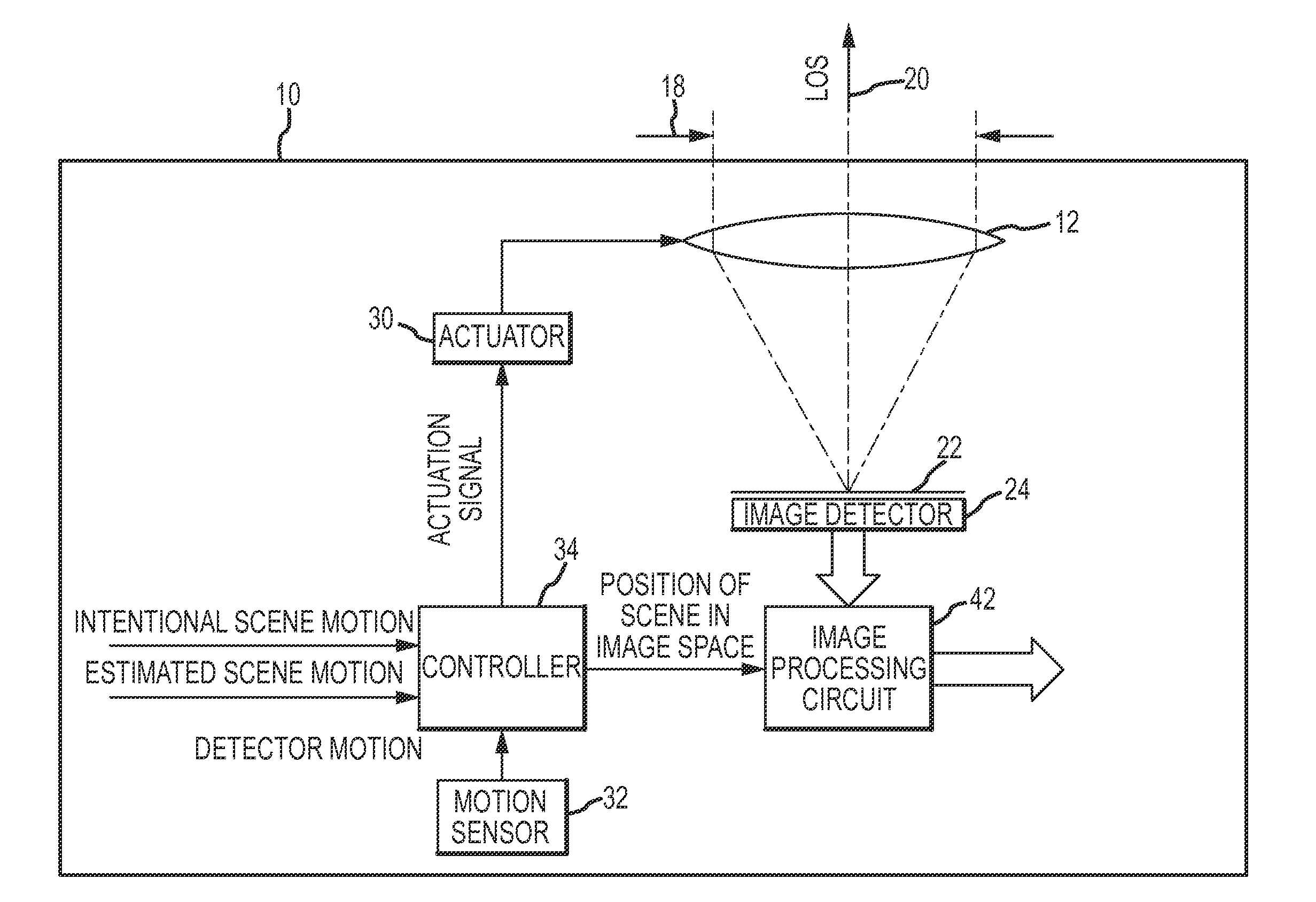
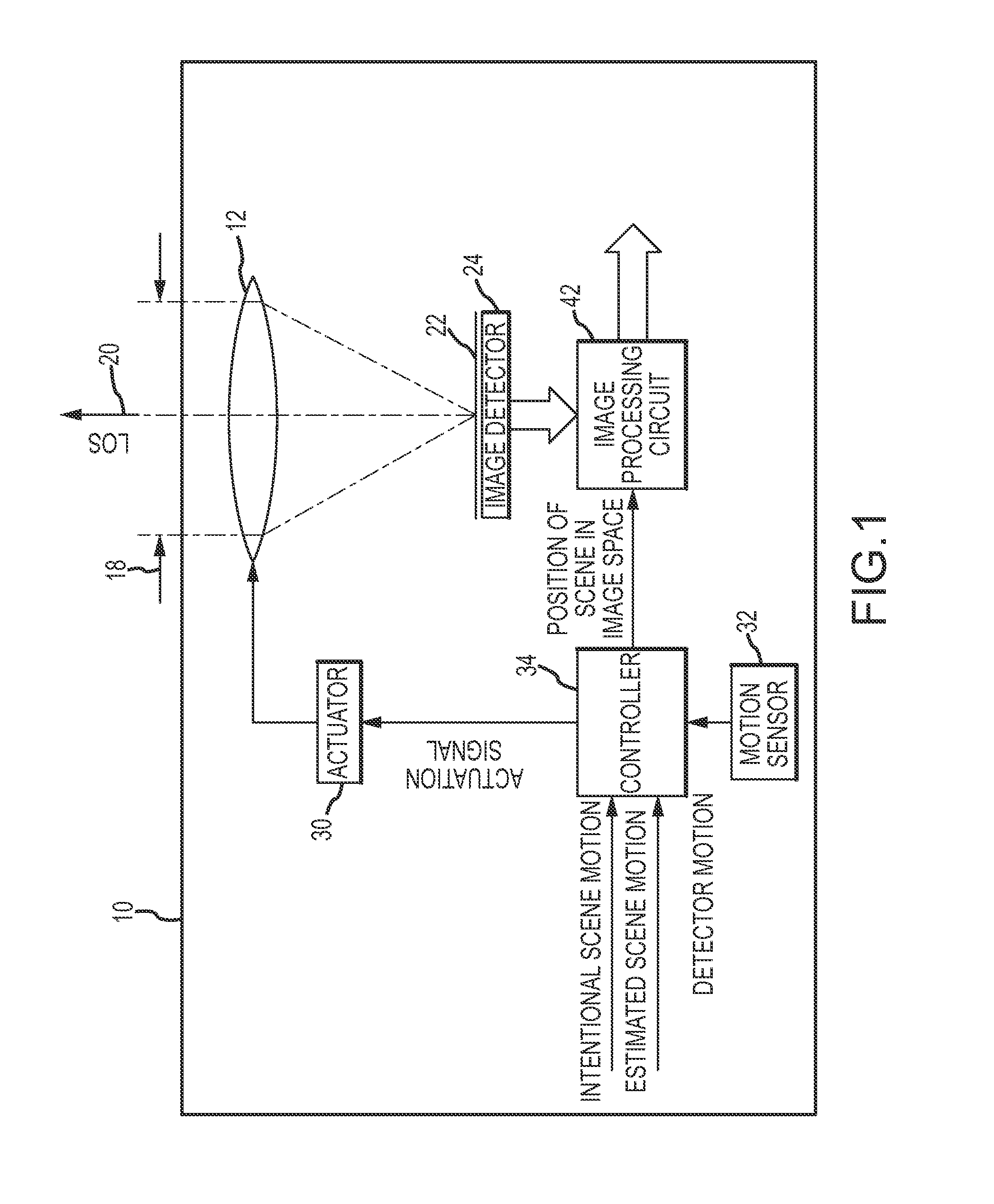
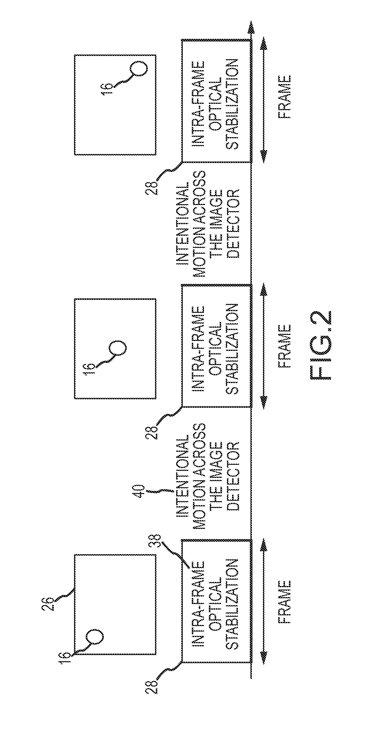
[0029]In an imaging system, in accordance with the present invention intentional scene motion across the image detector, and more particularly the rate of intentional scene motion is “decoupled” from smearing of the scene in the detected image by controlling the LOS motion between frames, as opposed to during frames, to produce the intentional scene motion in a discrete step across the image detector from frame-to-frame. The intentional scene motion may be quantized or provided as a sub-pixel dither signal to control the frame-to-frame sub-pixel phase of the detected image. In register / sum applications, this may substantially eliminate misregistration of the images at full-pixel resolution or allow for super-sampling of the images onto a higher resolution grid. The ability to decouple intentional scene motion from smearing and to control the frame-to-frame sub-pixel phase violates the accepted trade space of rate vs. smearing and defines a new trade space that relaxes the limitation...


PUM


Abstract

In an imaging system, intentional scene motion across the image detector from frame-to-frame, and more particularly the rate of intentional scene motion is “decoupled” from smearing of the scene in the detected image by applying the intentional scene motion in the interval between frames to produce the intentional scene motion in a discrete step across the image detector from frame-to-frame. The intentional scene motion may be quantized or provided as a sub-pixel dither signal to control the sub-pixel phase frame-to-frame. In register / sum applications, this substantially eliminates misregistration of the images and may allow for super-sampling of the images onto a higher resolution grid. The ability to decouple intentional scene motion from smearing and to control the sub-pixel phase defines a new trade space that relaxes the limitations on intentional scene motion across the image detector.

Description

BACKGROUND OF THE INVENTION[0001]1. Field of the Invention[0002]This invention relates to imaging systems, and more particularly to relaxing limitations on scene motion across the imager to address issues such as imaging system pointing and stabilization limitations, non-uniformity compensation (NUC), dead pixel clumps, burn-in mitigation, field-of-view (FOV) extension, super-sampling, pixel-phase induced noise in frame summing, and staying within the limits of optical stabilization actuators.[0003]2. Description of the Related Art[0004]Imaging systems image a field-of-view (FOV) of a scene along a line-of-sight (LOS) onto an image detector that captures images a certain frame rate. The “scene” is what the imaging system is looking at such as an object of interest in a background. It is well known and widely accepted that any motion Of the scene across the image detector produces smearing of the scene in the image during the frame. Such motion and smearing are tightly coupled. The h...

Claims


Application Information

Patent Timeline
Patent Type & Authority Applications(United States)
IPC IPC(8): H04N5/228H04N23/40
CPCH04N5/23264H04N23/682
Inventor WILLIAMS, DARIN S.
Owner RAYTHEON CO
Learn More