Huber Needle Assembly

a hubris and needle technology, applied in the field of hubris needles, can solve the problems of transferring a blood-borne pathogen to the user, presenting considerable risks to the medical practitioner using, and the needle rebounding and sticking the user,

Inactive Publication Date: 2013-09-12
MEDICAL COMPONENTS INC
View PDF7 Cites 19 Cited by
  • Summary
  • Abstract
  • Description
  • Claims
  • Application Information

AI Technical Summary

Problems solved by technology

They do, however, present considerable risks to the medical practitioners using them.
The force required to withdraw the needle from the self-sealing septum of the implanted port can cause the needle to rebound and stick the user.
This may result in transfer of a blood-borne pathogen to the user.
Further, it may expose the user to hazardous drugs.

Method used


Image

  • Huber Needle Assembly
  • Huber Needle Assembly
  • Huber Needle Assembly

Examples


Embodiment Construction

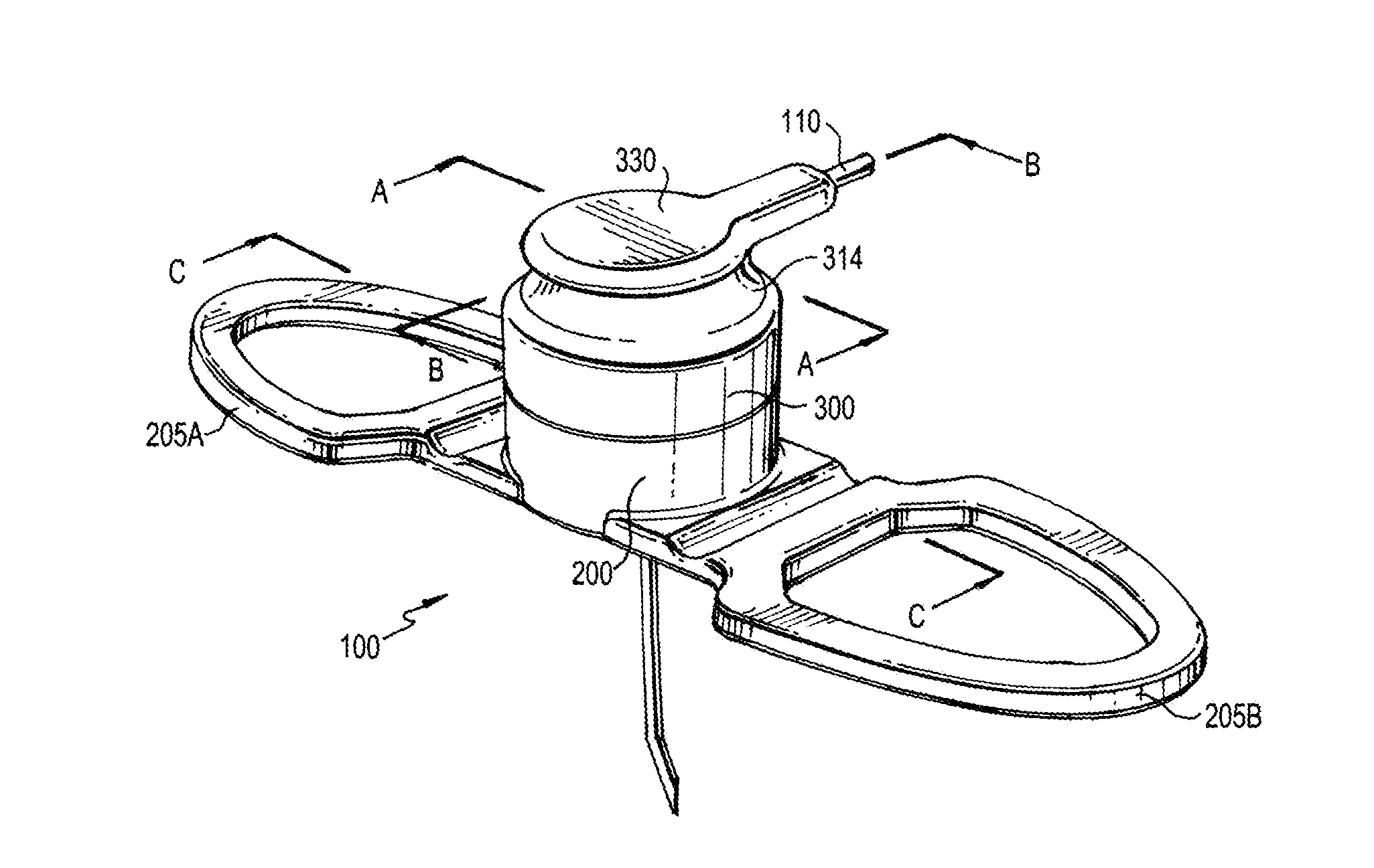
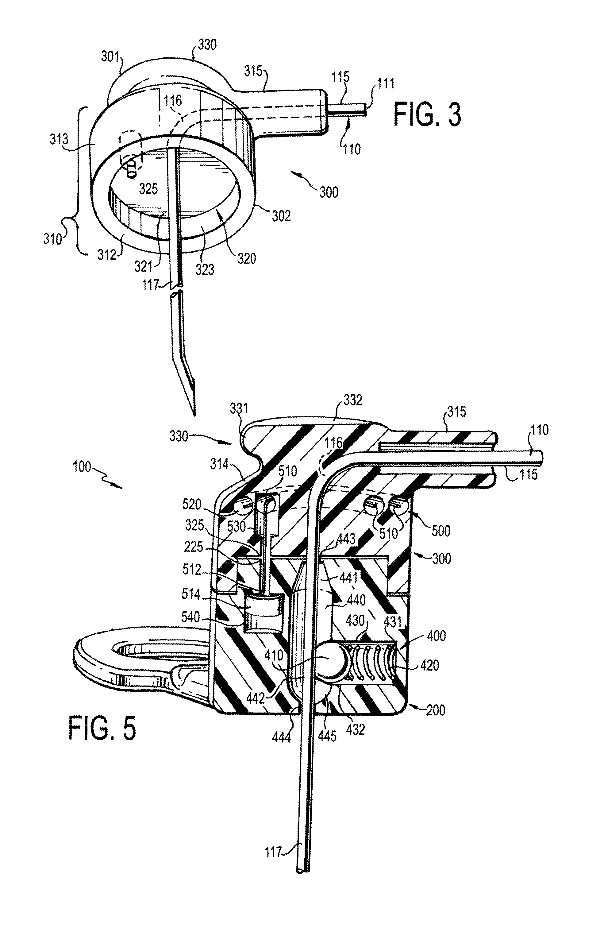
[0043]A Huber needle assembly desirably includes a needle safety or restraint mechanism and a needle tip block mechanism which together safely retain portions of the Huber needle that may contain blood products or medication within a needle impenetrable enclosure to reduce or minimize needle sticks to a medical practitioner.

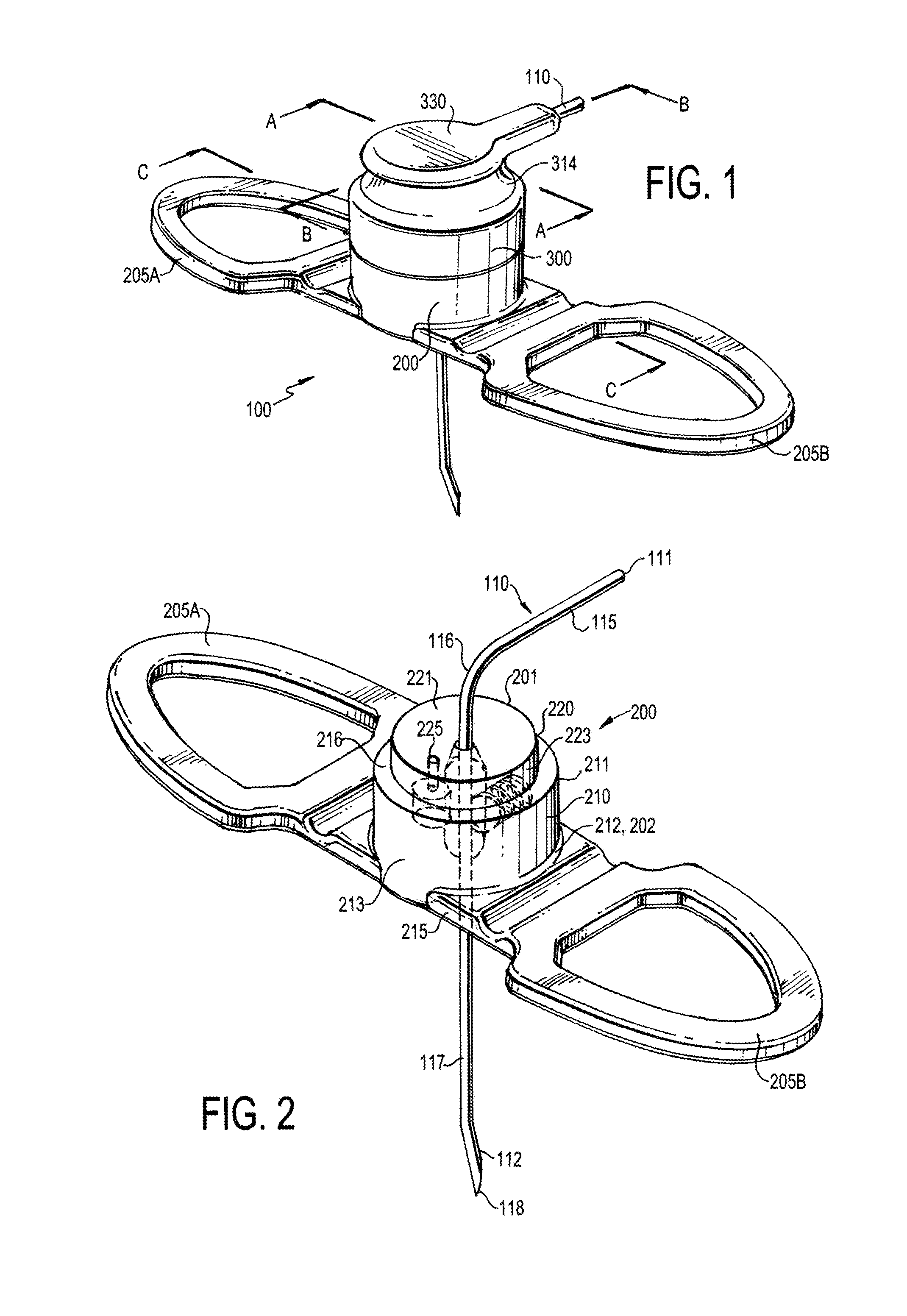
[0044]Referring now to FIG. 1, there is illustrated an exemplary embodiment of a Huber needle assembly, generally designated as 100, in accordance with an exemplary embodiment of the present invention. The Huber needle assembly 100 comprises a Huber needle 110, a base 200, and a housing 300 for the Huber needle 110. The Huber needle 110 is securely mounted within the housing 300 and is slidably disposed through the base 200. Except as otherwise described below, the components of the Huber needle assembly 100 are formed from plastic. The Huber needle 110 is formed from metal, such as stainless steel.

[0045]Illustrated in FIG. 2 is a perspective view of the base 200...


PUM


Abstract

A Huber needle assembly. The Huber needle assembly includes a housing, a Huber needle having a bent tip, a base through which the Huber needle is slidably disposed, a tip block mechanism, and a safety or restraint mechanism. The tip block mechanism includes a needle block slidably disposed within the base and urged by a spring to block the tip of the Huber needle when the tip of the Huber needle is retracted into the base. In one exemplary embodiment, the safety or restraint mechanism includes a cable having a first end anchored within the housing and a second end anchored within the base. The cable restrains movement of the housing relative to the base. In another exemplary embodiment, the safety or restraint mechanism includes a collar disposed within the base. The collar is configured to prevent passage of the bent tip of the Huber needle.

Description

CROSS REFERENCE TO RELATED APPLICATIONS[0001]This application claims the benefit of U.S. Provisional Application No. 61 / 607,845, entitled “Huber Needle Assembly” and filed Mar. 7, 2012, and U.S. Provisional Application No. 61 / 709,286, entitled “Huber Needle Assembly” and filed Oct. 3, 2012, the contents of which applications are incorporated herein by reference.FIELD OF INVENTION[0002]The present invention relates generally to needles for subcutaneous injections and, more specifically, to a Huber needle assembly comprising a tip block mechanism and a safety or restraint mechanism.BACKGROUND OF THE INVENTION[0003]Conventional Huber needle assemblies are widely used in hospitals and alternate care sites and are often used in conjunction with implanted ports. Such Huber needle assemblies provide non-coring Huber needles that are used to administer chemotherapy, IV fluids, medications, total parenteral nutrition, or to transfuse blood products through the implanted ports. The implanted ...

Claims


Application Information

Patent Timeline
Patent Type & Authority Applications(United States)
IPC IPC(8): A61M25/06
CPCA61M5/158A61M2005/1581A61M25/0625A61M2005/1587A61M2005/1586A61M5/3273A61M5/3275A61M39/0208A61M2005/325
Inventor FISHER, MARKLINDEN, CHRISTOPHERCIUCIU, CRISTIAN M.BIZUP, RAYMOND R.
Owner MEDICAL COMPONENTS INC
Why Eureka
Try Eureka