
Retractable needle assembly

Inactive Publication Date: 2007-11-13
BECTON DICKINSON & CO
View PDF162 Cites 143 Cited by
  • Summary
  • Abstract
  • Description
  • Claims
  • Application Information

AI Technical Summary

Benefits of technology

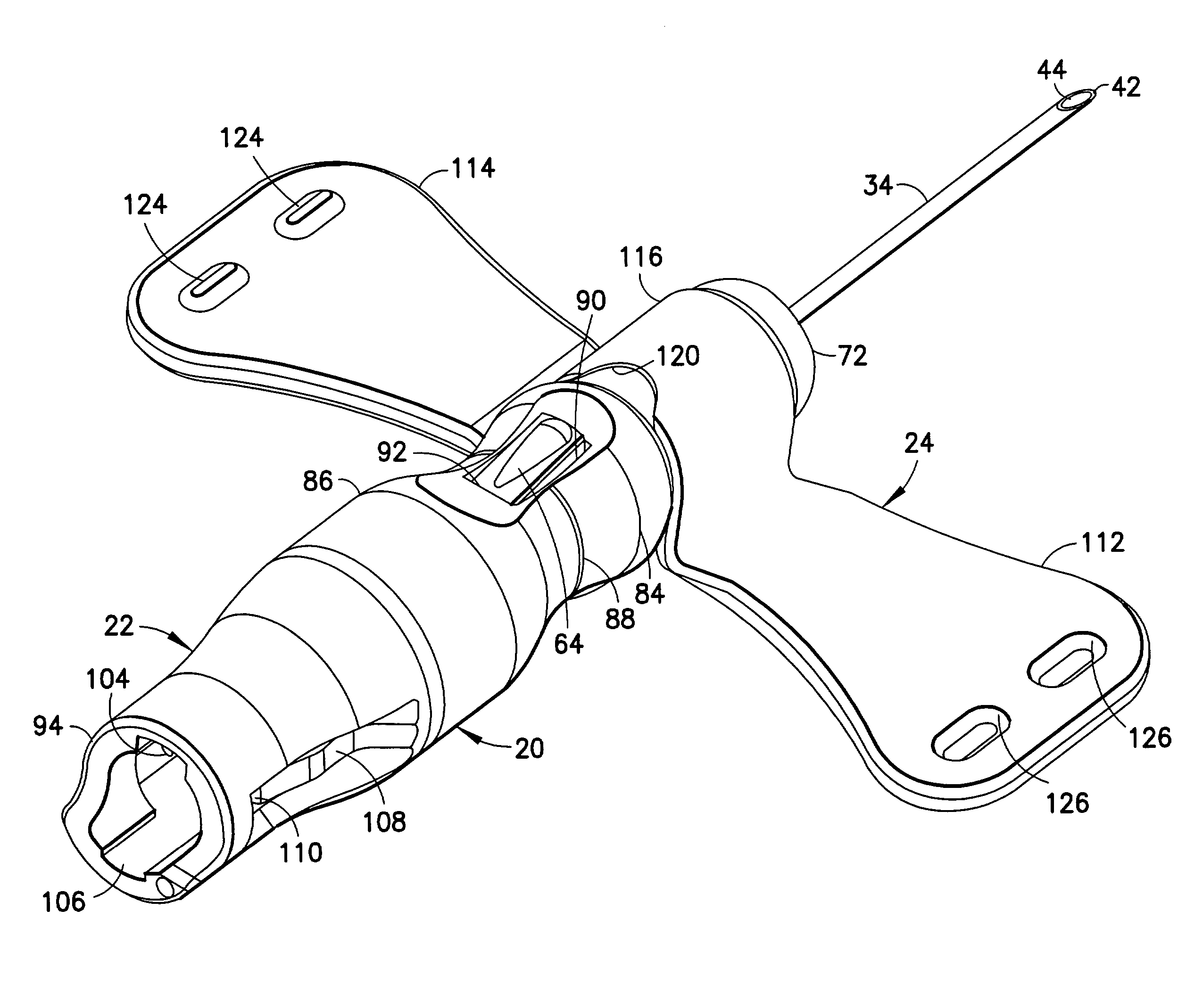
[0011]The barrel includes an actuation region that has an actuating aperture disposed and configured to permit engagement of the actuator button when the piercing element is in the distal position. Portions of the actuating region of the barrel may define a smaller cross-section than portions of the barrel either distally or proximally of the actuating region. Thus, the actuating aperture and the actuator button are recessed slightly relative to portions of the barrel on either longitudinal side of the actuating region to prevent inadvertent actuation that could displace the needle assembly relative to the barrel. Additionally, the recessed shape of the actuator region provides a visual cue to identify regions of the barrel that should be digitally accessed to retract the piercing element. This allows the user to locate the actuator button during use with or without visually seeing it and sometimes only relying on the change in tactile surface near the actuator region. The exterior shape of the barrel is preferably circular when viewed in a cross section perpendicular to the barrel's axis.
[0012]The barrel comprises means for preventing re-exposure of the piercing element after shielding has been effected. For example, the barrel may include an array of inwardly directed resilient fingers aligned to permit retraction of the piercing element relative to the barrel, but to prevent re-exposure of the retracted piercing element.
[0016]The hub and barrel of the apparatus preferably are formed from translucent or transparent materials to provide “venous indication” or “flash” when the apparatus is part of a fluid collection set. This allows the user to identify when venous blood has reached the fluid path proximal from the proximal end of the needle cannula and to identify when venous blood has reached the inside of the needle hub.
[0017]The apparatus may further include a dampening agent, such as a viscous or non-viscous dampening agent to alter the acceleration and velocity of piercing element. Viscous dampening agents include grease, oil, gel, gel resin, or any combination thereof and non-viscous dampening agents include biased flexible elements extending between the front and rear barrels or the needle hub. Preferably, the dampening agent is a material with an ability to temporarily elastically bond the coils of the spring together. Thus, when retraction is initiated by pushing the actuator button, the bond between adjacent coils achieved by the dampening agent slows the initial opening of the coils from the tightly compressed state of the spring in the collapsed condition. As a result, the dampening agent preferably provides a slower initial acceleration and hence reduces splatter.
[0019]The retractable apparatus is packaged with the piercing element in a distal position relative to the barrel. The packaging preferably is configured to prevent inadvertent actuation. The apparatus then is removed from its packaging for use. Use commences by folding the wings into face-to-face engagement with one another and holding the folded wings between a thumb and forefinger. The health care worker then pulls the protector from the apparatus to expose the distal end of the piercing element. The distal end of the piercing element then is guided into a blood vessel or other targeted location. The fitting that may be provided at the proximal end of the tubing may be placed in communication with a source or reservoir for fluid in those instances where the apparatus is part of a fluid collection set or an infusion set. The ordering of these steps may vary depending on whether the set is used for fluid collection or for infusion. Upon completion of the medical procedure, the health care worker merely depresses the actuator button. The depression of the actuator button releases the actuator button from the actuating aperture and permits the spring to propel the piercing element proximally and into the shielded position within the barrel. The locking structure on the barrel prevents complete proximal separation of the piercing element from the barrel and prevents re-exposure of the used piercing element.

Problems solved by technology

Accidental sticks with a needle cannula can be painful and can transmit disease.
A lack of familiarity with the specified operation of a shield for a particular medical device can lead to improper shielding and hence creates the potential for an accidental stick with a used needle cannula.
Devices that are mechanically simple may provide less effective shielding.
More secure shielding may require more complex manipulation of the device by the health care worker.

Method used


Image

  • Retractable needle assembly
  • Retractable needle assembly
  • Retractable needle assembly

Examples


Embodiment Construction

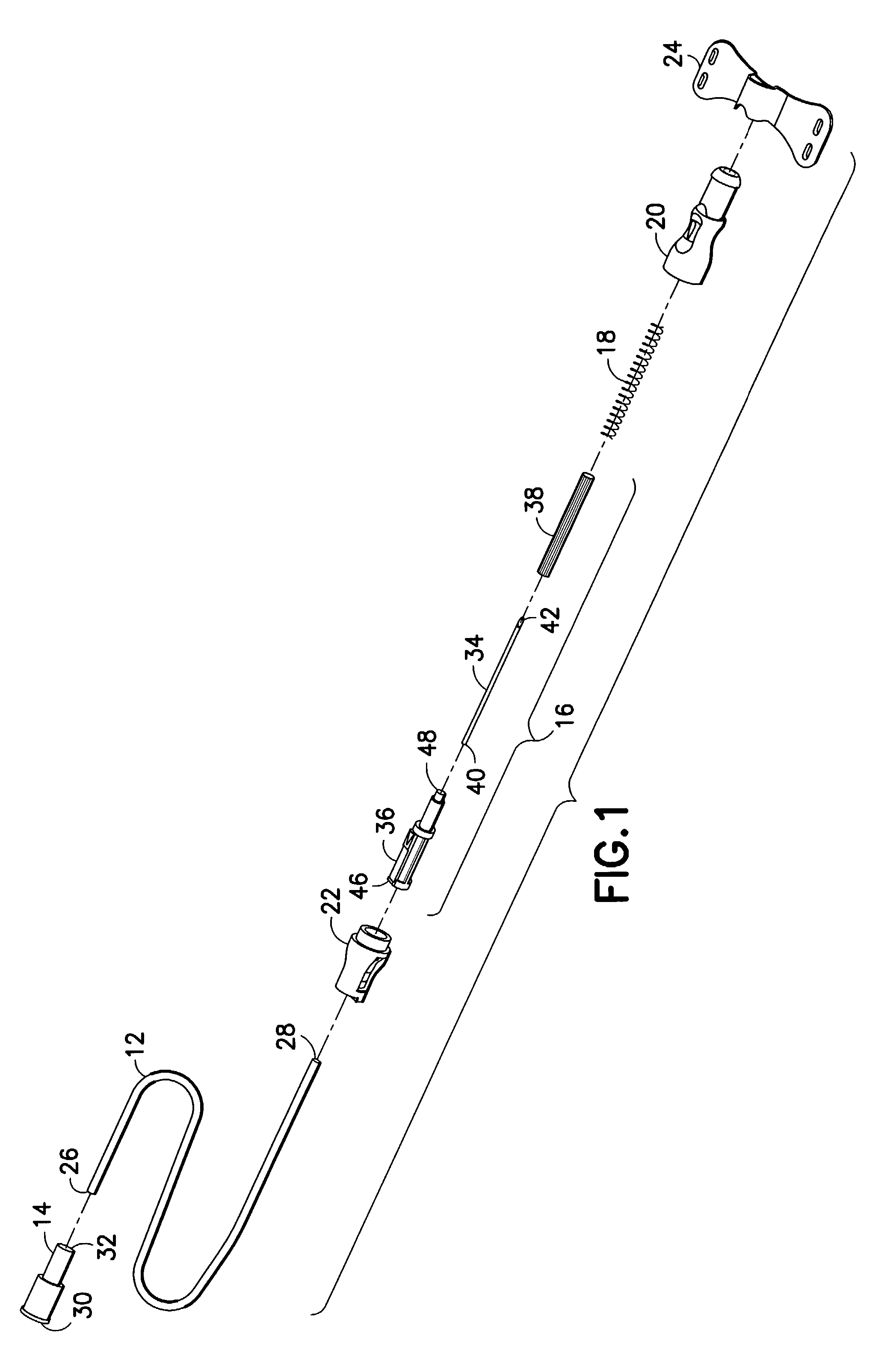
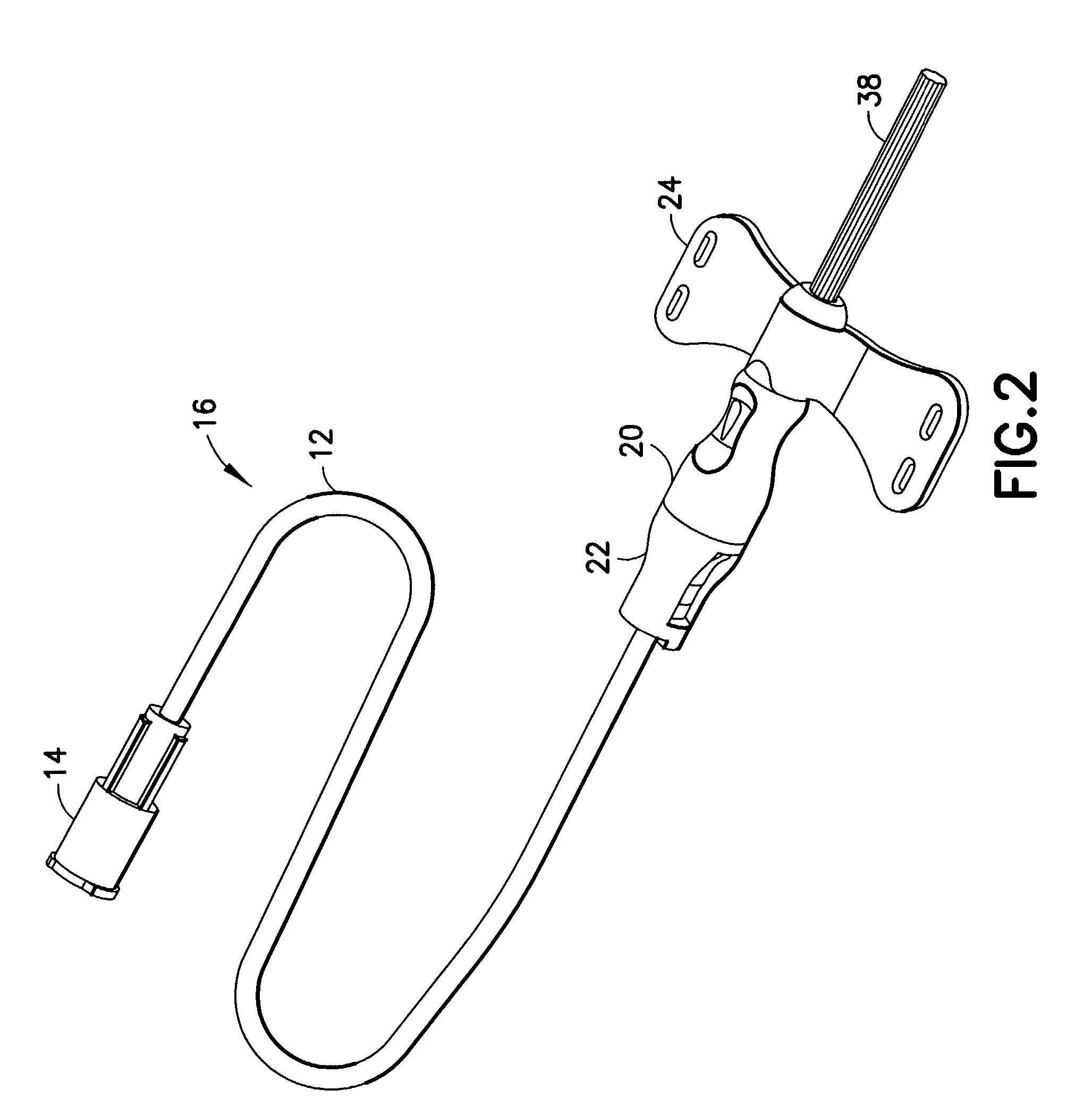
[0044]A fluid collection / infusion set in accordance with the subject invention is identified generally by the numeral 10 in FIGS. 1-3. Fluid collection / infusion set 10 includes a length of flexible plastic tubing 12, a proximal fitting 14, a needle assembly 16, a spring 18 and a barrel assembly that comprises a front barrel 20, a rear barrel 22 and a wing 24.

[0045]Tubing 12 includes a proximal end 26, a distal end 28 and a passage extending between the ends. Tubing 12 may be conventional intravenous tubing used in conventional blood collection sets or infusion sets.

[0046]Proximal fitting 14 is molded unitarily from a plastic material and includes a proximal end 30, a distal end 32 and a passage extending between the ends. Portions of the passage adjacent distal end 32 are configured to telescope tightly over proximal end 26 of tubing 12 so that the passage through tubing 12 communicates with the passage through connector 14. Proximal end 30 of fitting 14 defines a female luer connec...


PUM


Abstract

A fluid collection or infusion set is provided. The set includes flexible tubing with a fitting attached to a proximal end and a needle assembly attached to the distal end. The needle assembly includes a needle hub and a needle cannula secured in the hub. An actuator arm extends proximally and outwardly from the needle hub and has an actuator button at its free end. The needle assembly is disposed in a barrel and can move from a distal position where the needle cannula is exposed to a proximal position where the needle cannula is shielded. A spring is disposed in the barrel for propelling the needle assembly to the proximal position. The barrel includes an actuating aperture that receives the actuator button for locking the spring in a compressed condition. Depression of the actuator button enables the spring to propel the needle assembly into its proximal shielded position.

Description

RELATED APPLICATIONS[0001]This application claims priority on U.S. Provisional Patent Appl. No. 60 / 338,910, filed Oct. 24, 2001 and U.S. Provisional Patent Appl. No. 60 / 399,318, filed Jul. 26, 2002.FIELD OF THE INVENTION[0002]The invention relates to a medical apparatus with a piercing element.BACKGROUND OF THE INVENTION[0003]Fluid collection sets, intravenous infusion sets and catheters are employed respectively for collecting bodily fluids from a patient, for infusing liquids into a patient. Fluid collection sets and intravenous infusion sets include a length of flexible plastic tubing with a proximal end connected to a plastic fitting and a distal end connected to a needle assembly. The needle assembly includes a hub and needle cannula. A pair of flexible plastic wings is mounted to or near the hub. The wings can be folded into face-to-face engagement with one another, and hence define a convenient handle for gripping and manipulating the needle cannula. The wings also can be rot...

Claims


Application Information

Patent Timeline
IPC IPC(8): A61M5/00A61M5/32A61M25/06
CPCA61M25/0637A61M25/0631A61M5/3257A61M2005/3247
Inventor SAULENAS, WILLIAM G.WILKINSON, BRADLEY M.NIERMANN, VOLKERSWENSON, KIRK D.
Owner BECTON DICKINSON & CO
Learn More