Operator control method and operator control device for a vehicle

a technology for operator control and vehicle, applied in the direction of vehicle seats, program control, special data processing applications, etc., can solve the problem of frequent malfunction and achieve the effect of reducing the frequency of accidental activation

Active Publication Date: 2014-04-01
VOLKSWAGEN AG +1
View PDF38 Cites 23 Cited by
  • Summary
  • Abstract
  • Description
  • Claims
  • Application Information

AI Technical Summary

Benefits of technology

[0007]It is therefore an object of the present invention to reduce a frequency of an accidental activation of the specific operator control function.
[0009]In other words, the present invention avoids an accidental activation of the third operator control function in that at least the sensitivity of the first sensor is reduced compared to a sensitivity during a detection of the corresponding physical variable for the activation of the first operator control function. Depending on how the first sensor operates, the reduction of the sensitivity can lie in that the third threshold value is increased or reduced compared to the first threshold value, which depends on whether the first sensor detects an actuation via a reduction or an increase of the first physical variable.
[0011]Due to the dynamic trigger threshold (first or third threshold value) of the first sensor, an adjustment to different cases of use is possible, so that trigger thresholds of different levels apply to the different cases of use. Due to different sensor sensitivities between a simple sensor function (activation of the first operator control function) and a sensor function that is activated by a series of actions (activation of the third operator control function), the present invention can be adapted advantageously to different requirement profiles. The change of the sensitivity of the first sensor can thereby be established via the distance between the first and the third threshold value.
[0015]Further, the sensitivity of the second sensor for the activation of the third operator control function can also be changed. However, there are advantages, for example, a lower complexity, if only the sensitivity of the first sensor for the activation of the third operator control function is increased. This applies in particular when the second sensor is realized as a type of switch, as already stated at the outset.
[0016]The first sensor and the second sensor can be attached to the vehicle such that both sensors can be easily activated at the same time by one operator, i.e. for example, using only one hand.
[0017]In order that the third operator control function can be easily activated by the same operator, it is an advantage if the two sensors are located close to one another in terms of location.

Problems solved by technology

In the conventional art, however, a malfunction frequently occurs when an unlocking sensor and a locking sensor are accidentally actuated at the same time.

Method used


Image

  • Operator control method and operator control device for a vehicle
  • Operator control method and operator control device for a vehicle
  • Operator control method and operator control device for a vehicle

Examples


Embodiment Construction

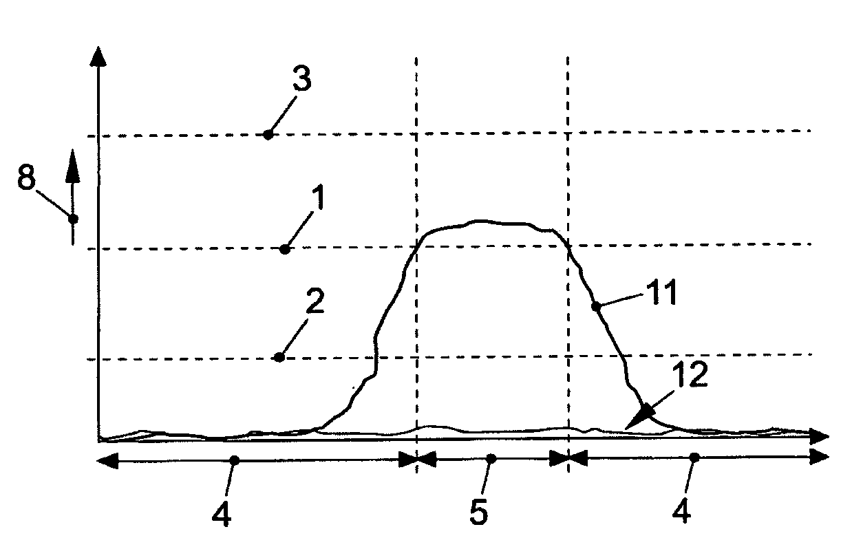
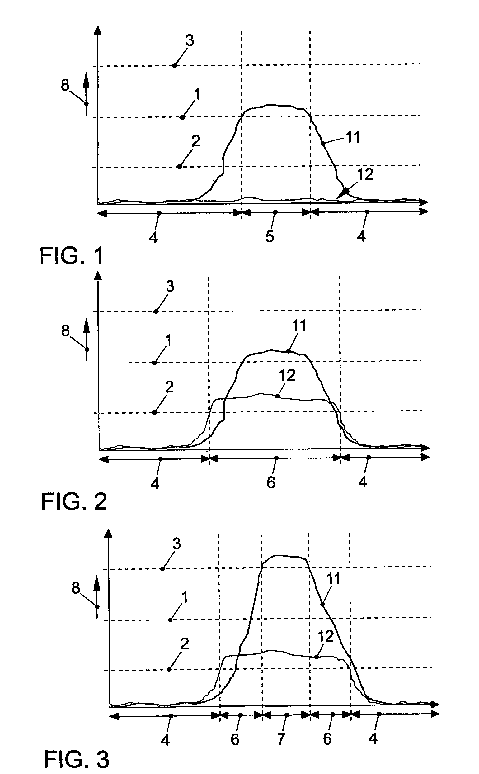
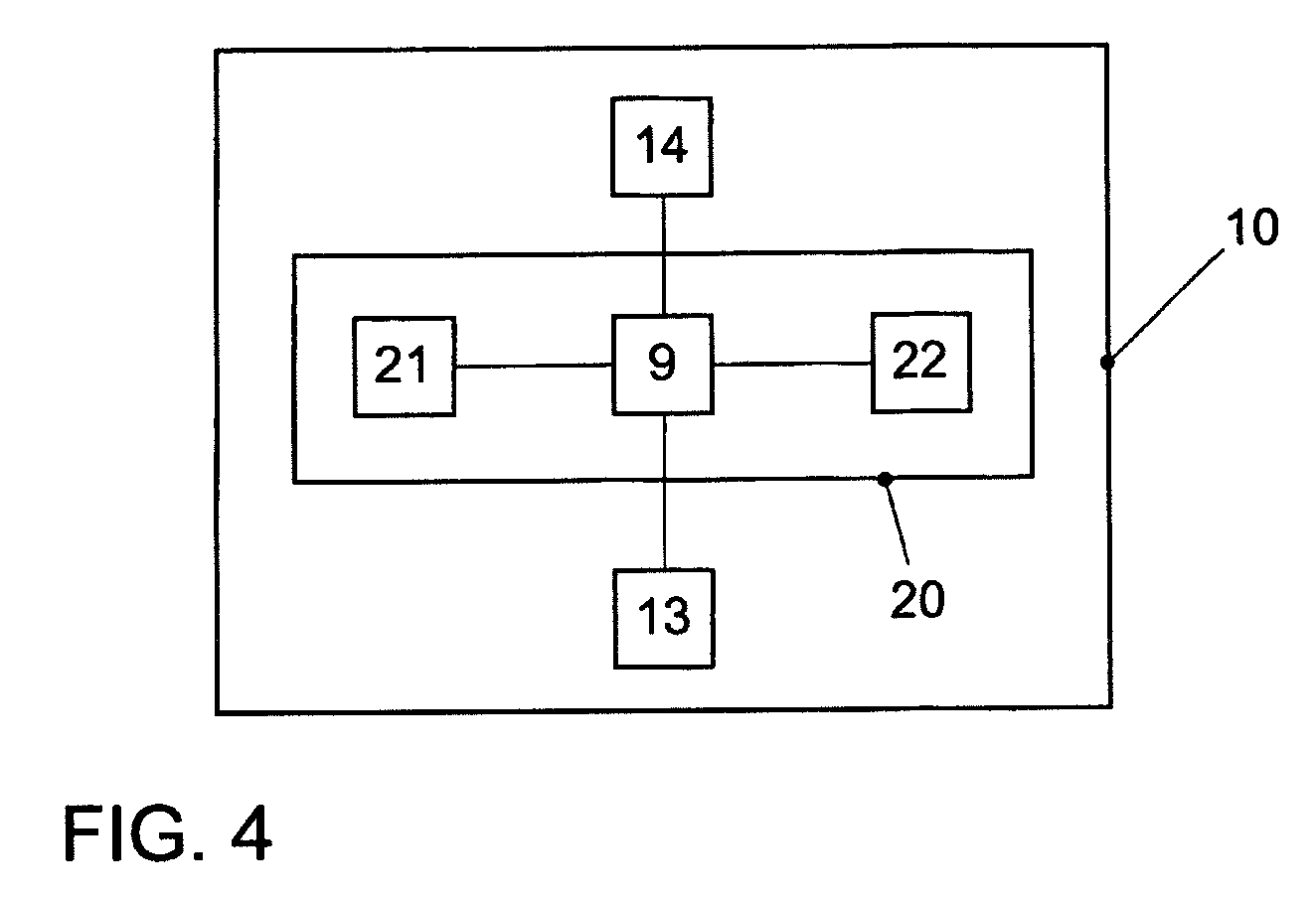
[0033]FIG. 1 shows a signal course 11 for the activation of a locking system of a vehicle. A first sensor (locking sensor) 21 shown in FIG. 4 is arranged at a specific location outside on a door handle of the vehicle, while a second sensor (unlocking sensor) 22 likewise shown in FIG. 4 is arranged on an inside of this door handle. In FIG. 1 the signal courses 11, 12 of the two sensors 21, 22 are shown over time, wherein a capacity 8 detected by the respective sensor 21, 22 is shown, since the sensors 21, 22 are capacitive sensors. The broken lines 1-3 running horizontally in FIG. 1 represent a first threshold value 1, a second threshold value 2 and a third threshold value 3. In FIG. 1 the capacitance course 11 of the first sensor 21 in a time interval shown by the reference number 5 exceeds the first threshold value 1, which leads to a locking signalization. This locking signalization leads to a locking of the vehicle when at the same time an ID transmitter authorized for this vehic...


PUM


Abstract

A first operator control function is activated if it is detected by means of a first sensor that a first physical variable is higher than a predetermined first threshold value. In a similar way, a second operator control function is activated if it is detected by means of a second sensor that a second physical variable is higher than a predetermined second threshold value. A third operator control function is activated if it is detected by means of the first sensor that the first physical variable is higher than a predetermined third threshold value and if at the same time it is detected by means of the second sensor that the second physical variable is higher than a predetermined fourth threshold value, the third threshold value being higher than the first threshold value.

Description

[0001]This nonprovisional application is a continuation of International Application No. PCT / EP2011 / 002004, which was filed on Apr. 20, 2011, and which claims priority to German Patent Application No. DE 10 2010 019 362.3, which was filed in Germany on May 5, 2010, and which are both herein incorporated by reference.BACKGROUND OF THE INVENTION[0002]1. Field of the Invention[0003]The present invention relates to an operator control method for activating an operator control function and an operator control device for activating this operator control function for a vehicle as well as a vehicle equipped in a corresponding manner.[0004]2. Description of the Background Art[0005]It is known from DE 10 2007 040 775 A1 to activate a certain operator control function when an unlocking sensor and a locking sensor of a vehicle are actuated at the same time.[0006]In the conventional art, however, a malfunction frequently occurs when an unlocking sensor and a locking sensor are accidentally actua...

Claims


Application Information

Patent Timeline
Patent Type & Authority Patents(United States)
IPC IPC(8): B60R22/00B60N2/02
CPCE05B85/01B60N2/0296B60N2/0244E05Y2800/424E05F15/1684E05Y2900/55B60N2/0228E05B77/32B60N2/0224E05F15/2092B60N2/0248E05Y2900/542E05Y2800/00Y10T70/7068E05F15/79Y10T70/739E05F15/695
Inventor WERNER, STEFANSCHARWALD, LOTHARGRAVE, DIETMARTHIELE, ANDREAS
Owner VOLKSWAGEN AG
Why Eureka
Try Eureka