Outer door grip, in particular for vehicles

a technology for vehicles and doors, applied in the field of outer door grips, can solve the problems of affecting the safety of the blocking member, affecting the safety of the door handle, and reducing the safety of the blocking member, so as to avoid the unusable effect of actuating the handl

Active Publication Date: 2013-04-23
HUF HULSBECK & FURST GMBH & CO KG
View PDF16 Cites 21 Cited by
  • Summary
  • Abstract
  • Description
  • Claims
  • Application Information

AI Technical Summary

Benefits of technology

[0008]Therefore it is an object of the present invention to create an outer door grip of the initially recited kind, which outer door grip can be employed at all doors of the vehicle and which outer door grip prevents an unintentional opening of the vehicle door through a crash from the most different directions.
[0011]The blocking member has available two blocking positions. The blocking member passes based on the inertia of its mass into a first blocking position through the deflection caused by the crash in case of a crash out of a first direction. The blocking member is deflected in a different direction and passes this way into a second blocking position if however the crash occurs from a second direction which is at least in part approximately opposite to the first crash direction. This is associated with the advantage that an unintentional opening of the door is avoided, independent of the direction from which the crash occurs. Also an unintentional actuation of the handle and a therewith associated opening of the door through the vibrations caused through the impact of the crash are prevented. In addition, it is possible to furnish an outer door grip which can be mounted on all doors, in particular on the two sides of the vehicle, and which nevertheless does justice to the requirements of crash safety. This is more cost advantageous in the production and also saves costs for storing. The blocking member blocks according to the present invention the handle under intermediate switching and positioning of a blocking lever. This blocking lever is guided in a connecting link guide and is moved together with the normal actuation of the handle. However just this motion of the blocking lever is prevented by the blocking member in case of a crash, thereby also the handle cannot be moved and the door does not open unintentionally. A good point of attack for the blocking member is provided in its blocking position by way of the intermediate switching and positioning of the blocking lever. The connecting link guide furnishes a simple and error insensitive possibility of actuation and motion of the blocking lever.
[0015]According to a preferred embodiment, the blocking member is spring loaded, wherein the spring load takes care that the blocking member remains in its release position in the standard situation. It is thereby avoided on the one hand that the blocking member becomes deflected from its release position into one of its blocking positions through standard motions of the vehicle, for example upon driving around a curve, and that an actuation of the handle and therewith an opening of the door is not any longer possible. It is also important that after an occurrence of a crash, persons can open the vehicle door from the outside in order to liberate for example injured vehicle passengers or children from the vehicle. The spring loading therefore advantageously takes care that after the occurrence of a crash and after the decaying of the vibrations caused by this crash, then the blocking member is transferred again into its release position such that the doors can be opened.

Problems solved by technology

Since the blocking member is rarely in action naturally, it could occur on the other side that the blocking member seizes or, respectively, becomes clamped or that the surfaces corrode.
A safe functioning of the blocking member is not any longer assured in a then occurring case of a crash in such a situation.

Method used


Image

  • Outer door grip, in particular for vehicles
  • Outer door grip, in particular for vehicles
  • Outer door grip, in particular for vehicles

Examples


Embodiment Construction

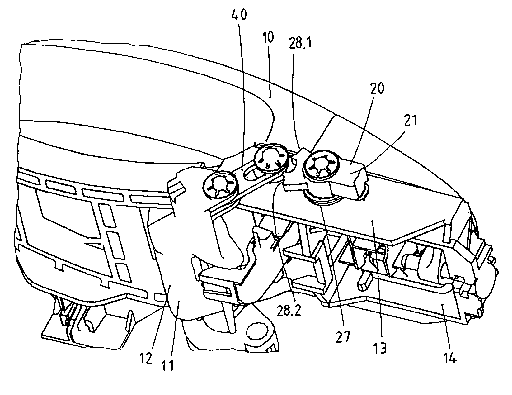
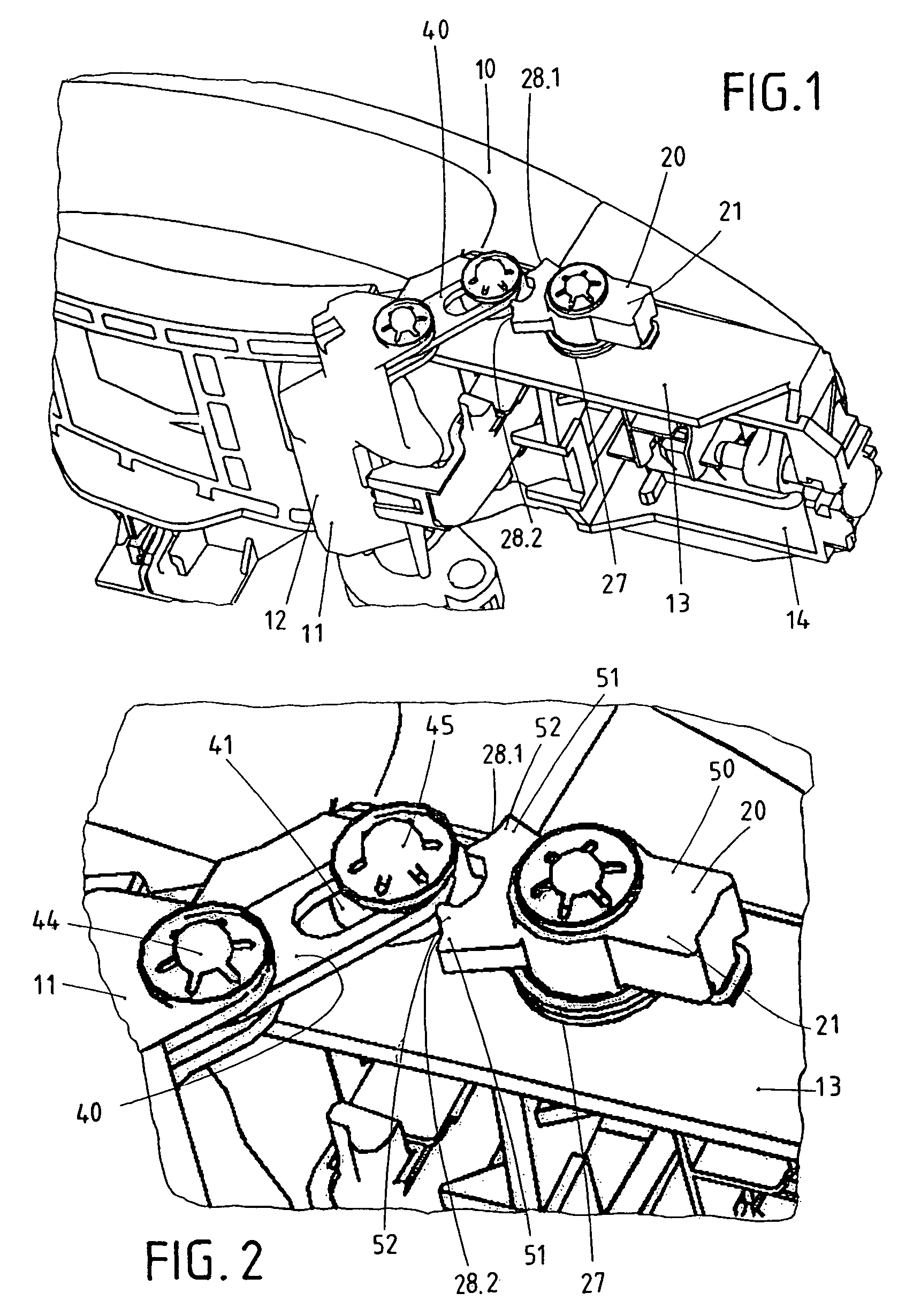
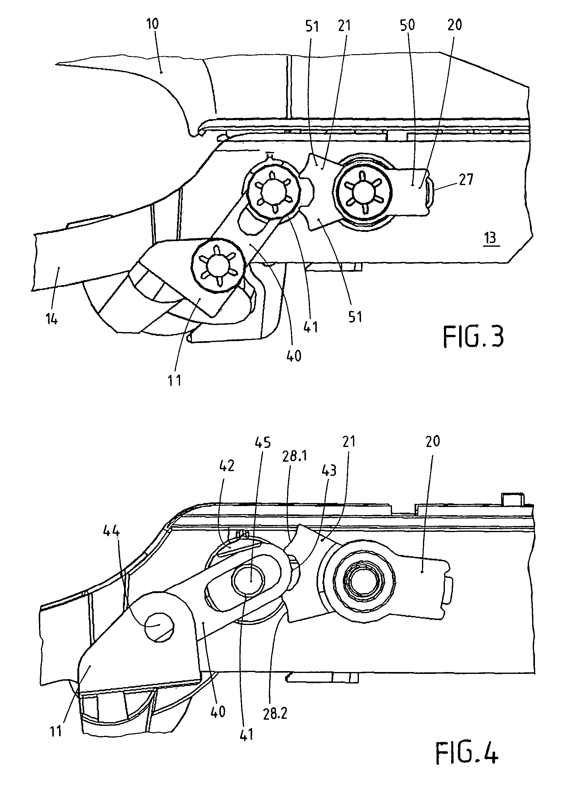
[0037]FIG. 1 shows that the outer door grip with the handle 10. A mass balancing weight 12 is furnished and serves simultaneously as a co-moving element 11. The blocking the leaver 40 is pivotally hinged at the mass balancing weight 12. The bearing bow 14 serves as a fixed element 13. The other side of the blocking lever 40 is disposed in the connecting link guide 41 attached at the bearing bow 14. The blocking member 20 is also disposed at the bearing bow 14, which blocking member 20 is disposed 4 its release position 21. The spring 27 is disposed below the blocking member 20, wherein the spring 27 strives to hold the blocking member 20 in its release position 21. The spring 27 is formed such that it opposes the deflections of the blocking members 20 in two directions.

[0038]This can be recognized from FIG. 2 in some more detail. The blocking member 20 exhibits two limit stops 28.1 and 28.2. The blocking member 20 engages with the one of its limit stops 28.1, 28.2 with a counter lim...


PUM


Abstract

The invention concerns an outer door grip, in particular for vehicles. The outer door grip exhibits a handle (10), which can operate a lock disposed in the door upon actuation. The outer door grip exhibits a pivotal blocking member (20), which is normally placed in its ineffective release position (21) and therewith enables actuation of the handle (10). The blocking member (20) passes into an effective blocking position (22.1, 22.2) based on the inertia of the mass of the blocking member (20) in case of a crash, whereby the handle (10) becomes blocked. The blocking member (20) has available two blocking positions (22.1, 22.2), wherein the blocking member (20) moves into the first blocking position (22.1) upon a crash out of a first direction (30.1) and wherein the blocking member (20) moves into the second blocking position (22.2) upon a crash out of a second direction (30.2) located opposite to the first direction (30.1). A blocking lever (40) is furnished which is intermediately switched in the blocking position (22.1, 22.2) of the blocking member (20). The blocking lever (40) is thereby guided in a kind of connecting link guide (41).

Description

BACKGROUND OF THE INVENTION[0001]1. Field of the Invention[0002]The invention relates to an outer door grip, in particular for vehicles, with a manually actuatable handle, wherein the handle upon activation can interact with a lock disposed in a door and with a pivotal blocking member, which is disposed normally in an ineffective release position and therewith allows to actuate the handle, which however based on the inertia of its mass passes into an effective blocking position in case of a crash and therewith blocks the handle, wherein two blocking positions are available to the blocking member, and wherein the blocking member passes into a first blocking position in case of a crash from a first direction and wherein the blocking member passes into a second blocking position in case of a crash from a second direction disposed opposite to the first direction.[0003]2. Brief Description of the Background of the Invention Including Prior Art[0004]Such outer door grips are used in a var...

Claims


Application Information

Patent Timeline
Patent Type & Authority Patents(United States)
IPC IPC(8): E05B3/00E05C3/00E05B77/54
CPCE05B77/06E05B85/16Y10T292/57
Inventor MULLER, ULRICHKILIAN, MARIONMULLER, DIRK
Owner HUF HULSBECK & FURST GMBH & CO KG
Why Eureka
Try Eureka