Heat exchanger and air conditioner equipped with same

Inactive Publication Date: 2013-09-19
SHARP KK
View PDF12 Cites 10 Cited by
  • Summary
  • Abstract
  • Description
  • Claims
  • Application Information

AI Technical Summary

Benefits of technology

[0030]According to the present invention, even if condensate water is formed on an outermost fin positioned at a lower portion of a heat exchanger, or condensate water

Problems solved by technology

In a side-flow type parallel-flow heat exchanger, if condensate water is accumulated on surfaces of flat tubes or of corrugated fins, an area of an air flow passage is narrowed by the water, so that heat exchange performance is deteriorated.
Such frost may even turn into ice.
When, as in the configurations described in the above patent documents,

Method used


Image

  • Heat exchanger and air conditioner equipped with same
  • Heat exchanger and air conditioner equipped with same
  • Heat exchanger and air conditioner equipped with same

Examples


Embodiment Construction

[0054]With reference to the appended drawings, the following describes embodiments of the present invention.

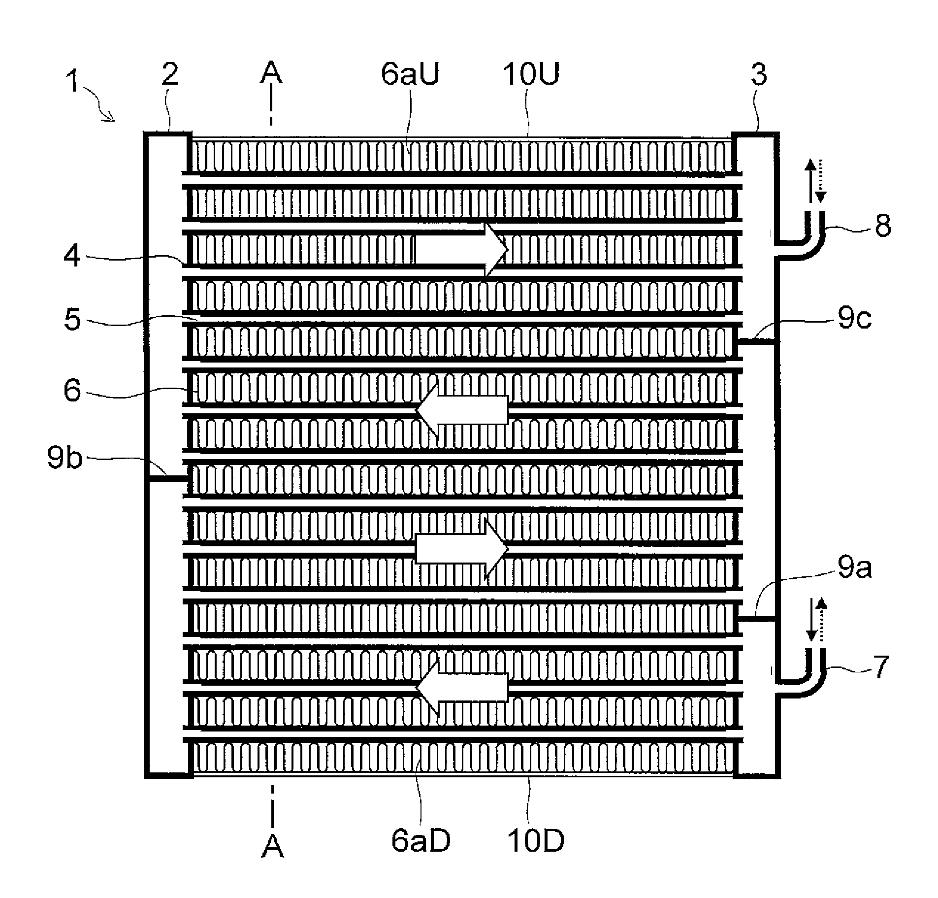
[0055]FIGS. 22 and 23 show a basic structure of a side-flow type parallel-flow heat exchanger. In each of FIGS. 22 and 23, an upper side of the figure is an upper side of the heat exchanger, and a lower side of the figure is a lower side of the heat exchanger. In a heat exchanger 1, two perpendicular header pipes 2 and 3 are arranged parallel to each other at an interval therebetween in a horizontal direction, and between the header pipes 2 and 3, a plurality of horizontal flat tubes 4 are arranged at a predetermined pitch in a perpendicular direction. Each of the flat tubes 4 is an elongated metal member formed by extrusion and has therein a refrigerant passage 5 for a refrigerant to flow therethrough. The flat tubes 4 are arranged with an extrusion direction thereof, which is also a longitudinal direction thereof, set to be horizontal, and thus a direction in which a refrige...


PUM


Abstract

The heat exchanger (1) comprises: two header pipes (2),(3) arranged in parallel with an interval therebetween; a plurality of flat tubes (4) which are arranged between the header pipes and which place coolant paths (5) provided therein in communication with the interior of the header pipes; a plurality of fins (6) attached to the flat surface of each flat tube; and side sheets (10U), (10D) attached to an outside of the fins (6aU), (6aD), which are positioned farthest outward among the plurality of fins. The side sheet (10D) positioned in the bottom part of the heat exchanger (1) has a plurality of notches (11) formed at intervals from each other on the edge of the side where condensed water collects in the heat exchanger (1). The notches are each provided with a width sufficient for covering the interval pitch (P) of the fin by several pitch lengths.

Description

TECHNICAL FIELD[0001]The present invention relates to a side-flow type parallel-flow heat exchanger and an air conditioner equipped with the same.BACKGROUND ART[0002]A parallel-flow heat exchanger has a configuration in which a plurality of flat tubes are arranged between a plurality of header pipes such that a plurality of refrigerant passages in the flat tubes communicate with interiors of the header pipes, and fins such as corrugated fins are disposed between the flat tubes. Such a parallel-flow heat exchanger is widely used in vehicle air conditioners, outdoor units of air conditioners for buildings, and so on.[0003]In the parallel-flow heat exchanger, the corrugated fins may be installed exclusively between the flat tubes or may be mounted therebetween and also to an outward facing surface of each outermost positioned one of the plurality of flat tubes. Examples of the latter case can be seen in Patent Documents 1 to 3.[0004]A heat exchanger described in Patent Document 1 is a ...

Claims


Application Information

Patent Timeline
IPC IPC(8): F28D1/053F28F1/04F28F1/30
CPCF24F1/18F28F9/001F28F17/005F28D1/0471F28F1/126F25B39/00F28F1/04F28F1/30F28D1/05333F28D2021/007F28D2021/0071F28D1/05358
Inventor HAMAGUCHI, SATOSHIUENO, MADOKA
Owner SHARP KK
Why Eureka
Try Eureka