
Electric Drive Axle Configuration

Active Publication Date: 2013-09-19
DEERE & CO
View PDF12 Cites 22 Cited by
  • Summary
  • Abstract
  • Description
  • Claims
  • Application Information

AI Technical Summary

Benefits of technology

The present disclosure describes a front axle system for vehicles, such as motor gradders, that includes an electric motor and a shaft coupled to the motor. The front axle system also includes a steering pivot and a wheel lean pivot, which work together to define the steering axis and the lean axis of the vehicle. A constant-velocity joint is disposed at the intersection of the steering axis and lean axis. The front axle system can also include a final drive assembly and a second gear to provide additional power and better traction. The technical effects of this system include improved steering and better traction for the vehicle, as well as increased power and efficiency.

Problems solved by technology

In particular, an electric motor can be larger in size compared to a hydraulic motor and thus packaging the electric motor within a conventional final drive assembly is problematic due to space constraints.
Due to its larger size, however, the electric motor will contact a portion of the front frame and reduce the overall performance of the vehicle.
For instance, if an electric motor is packaged in the conventional final drive assembly, the vehicle would likely have reduced steering capabilities and require changes to the pivot points of the axle (and thus possibly negatively affect the axle's lean capabilities).
In addition, if the electric motor were mounted at the same location in a conventional final drive assembly, wiring issues would arise as cables between the motor and other parts of the vehicle would have to flex for many steering and wheel lean movement thereby inducing problems in the wiring system.

Method used


Image

  • Electric Drive Axle Configuration
  • Electric Drive Axle Configuration
  • Electric Drive Axle Configuration

Examples


Embodiment Construction

[0023]The embodiments of the present invention described below are not intended to be exhaustive or to limit the invention to the precise forms disclosed in the following detailed description. Rather, the embodiments are chosen and described so that others skilled in the art may appreciate and understand the principles and practices of the present invention.

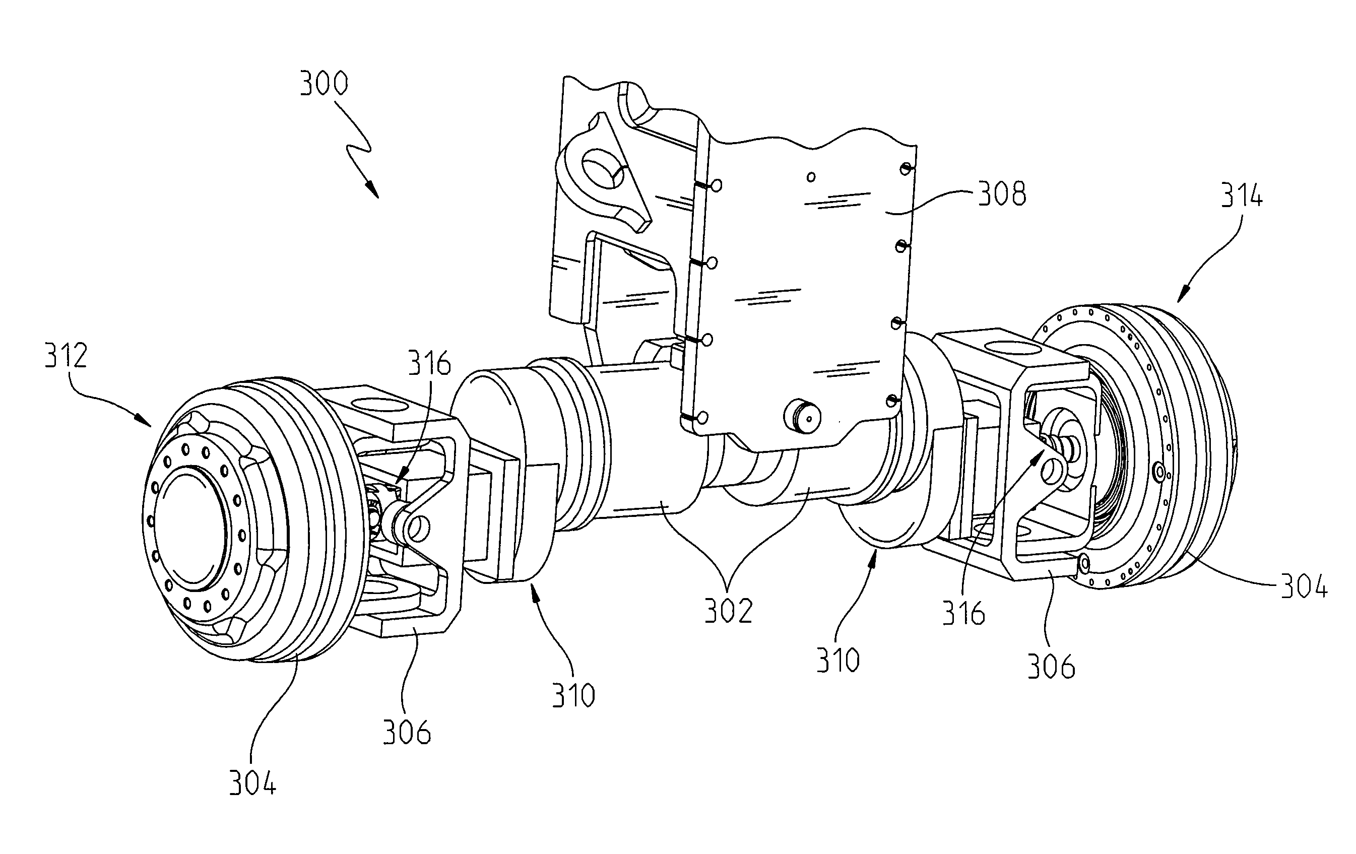
[0024]In the present disclosure, many of the disadvantages described above regarding converting a conventional front axle to an electric drive application can be overcome with the front axle shown in FIG. 3. In FIG. 3, an exemplary embodiment of a front axle 300 coupled to a body frame 308 of a motor grader is shown. However, a similar design of the front axle 300 can be accommodated in other work machines as well. The front axle 300 includes a first side 312 and a second side 314 to which a traction device (e.g., wheel) is coupled. Each traction device (not shown) can be powered by an electric motor 302, of which there is a moto...


PUM


Abstract

The present disclosure provides a front axle of a vehicle including a motor disposed near the center of the axle and a shaft coupled at one end thereof to the motor, where the shaft defines a first axis. A first gear is coupled to a second gear, the first gear being coupled to the shaft at an end opposite the motor and being disposed along the first axis. The second gear is disposed along a second axis, where the first axis and second axis are substantially parallel to but spaced from one another. A steering pivot defines a steering axis about which a final drive assembly pivots and a wheel lean pivot defines a lean axis about which the final drive pivots. The lean axis is substantially perpendicular to the steering axis. A constant-velocity joint is disposed at the intersection of the steering axis and lean axis.

Description

FIELD OF THE INVENTION[0001]The present invention relates to a front wheel axle of a work vehicle, and in particular, to an electric drive axle configuration that provides for a full range of motion about a steering pivot and wheel lean pivot.BACKGROUND OF THE INVENTION[0002]Work vehicles, such as a motor grader, can be used in construction and maintenance for creating a flat surface. When paving a road, a motor grader can be used to prepare a base foundation to create a wide flat surface for asphalt to be placed on. A motor grader can include two or more axles, with an engine and cab disposed above the axles at the rear end of the vehicle and another axle disposed at the front end of the vehicle. A blade is attached to the vehicle between the front axle and rear axle.[0003]The present disclosure is not exclusively directed to a motor grader, but rather can extend to other powered vehicles as well. For exemplary and illustrative purposes, however, the present disclosure will focus o...

Claims


Application Information

Patent Timeline
IPC IPC(8): B62D9/04F16H1/22B60K7/00
CPCB60K7/00E02F3/7663Y10T74/19019B60K17/306F16H1/22B60K2007/0053B60K17/043B60K7/0007B62D9/04B60Y2200/411
Inventor BINDL, REGINALD M.
Owner DEERE & CO
Features
  • Generate Ideas
  • Intellectual Property
  • Life Sciences
  • Materials
  • Tech Scout
  • Unparalleled Data Quality
  • Higher Quality Content
  • 60% Fewer Hallucinations
Learn More