Battery pack

Inactive Publication Date: 2013-09-19
CALSONIC KANSEI CORP
View PDF10 Cites 3 Cited by
  • Summary
  • Abstract
  • Description
  • Claims
  • Application Information

AI Technical Summary

Benefits of technology

[0004]The present invention was developed to solve such a problem and aims to cause cooling air to flow to

Problems solved by technology

However, the above invention has a problem that a duct as a separate component has to be arrang

Method used


Image

  • Battery pack
  • Battery pack
  • Battery pack

Examples


Embodiment Construction

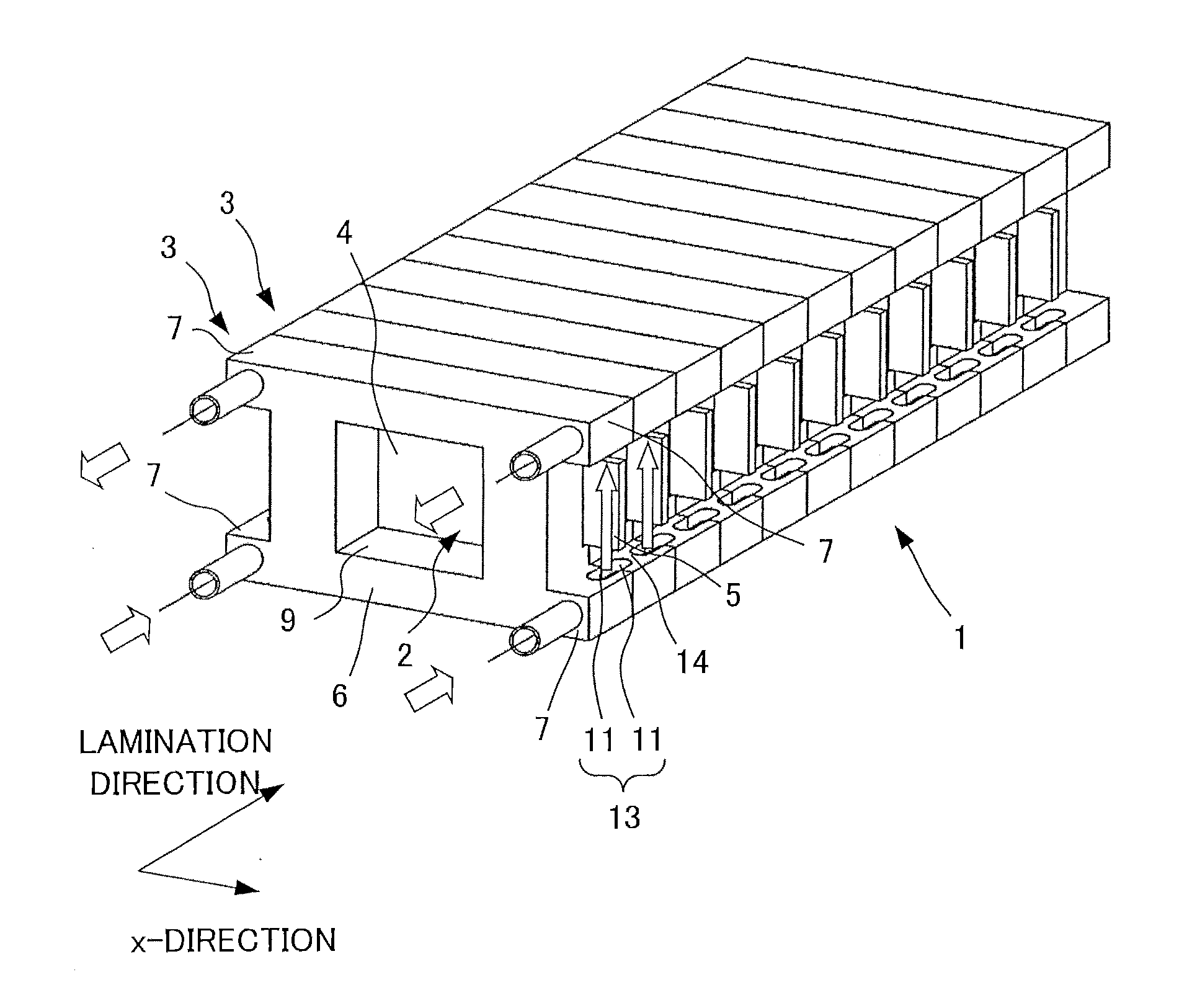
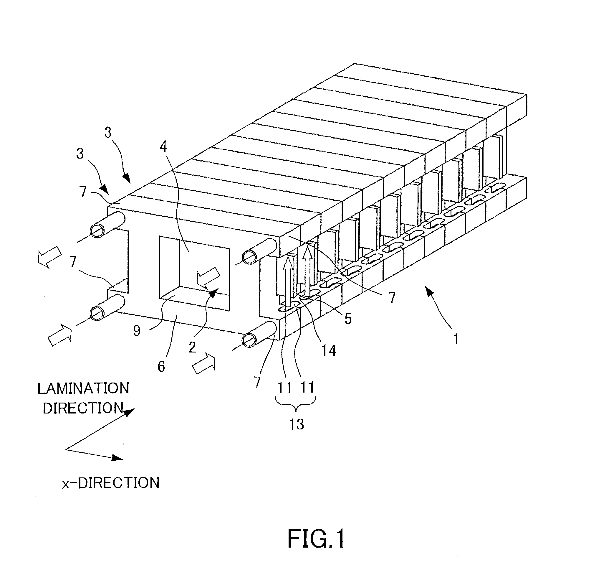
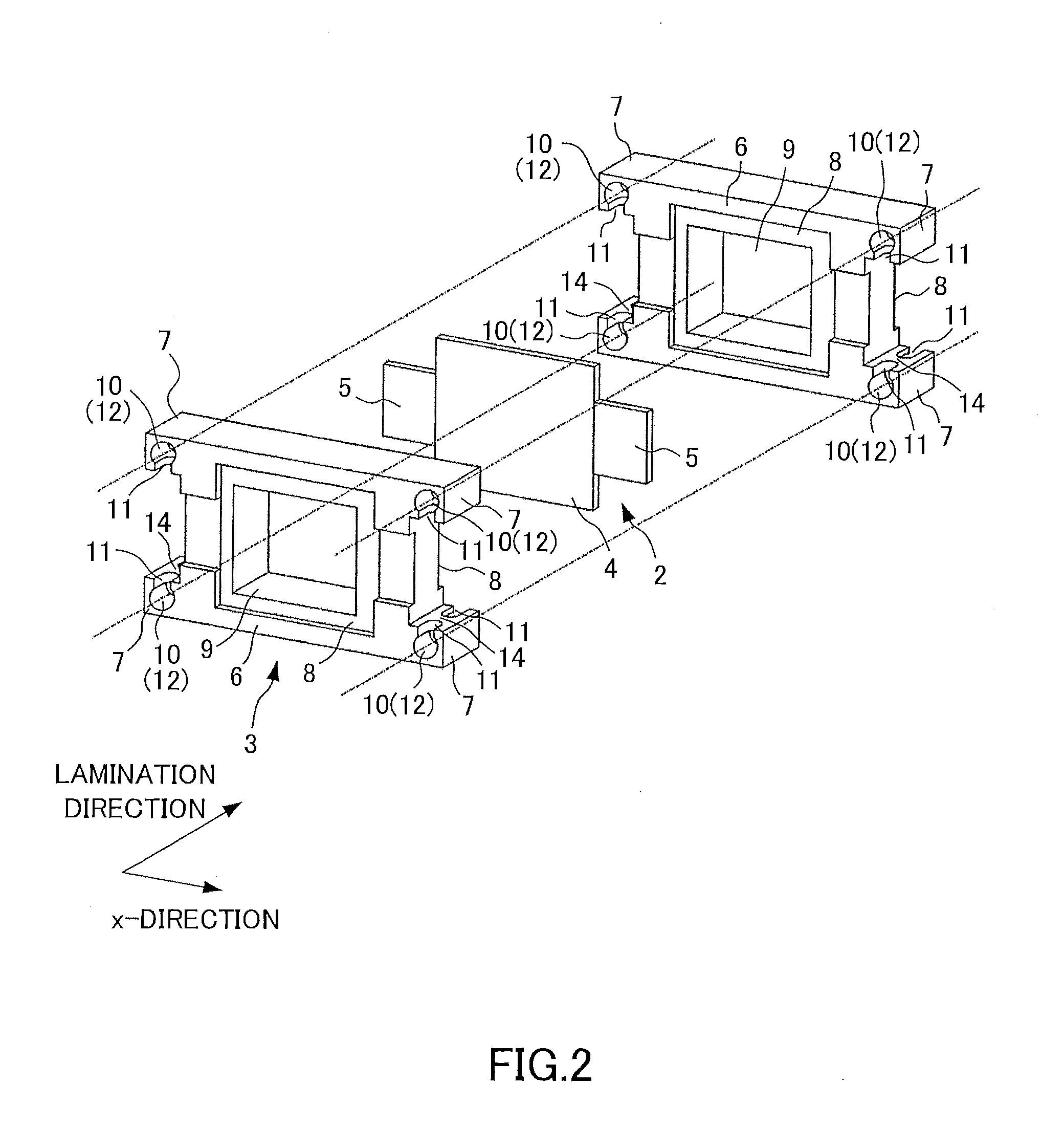
[0010]A battery pack of an embodiment of the present invention is described using FIGS. 1 and 2. FIG. 1 is a perspective view of the battery pack of the embodiment. FIG. 2 is an exploded perspective view showing a portion of the battery pack of this embodiment.

[0011]The battery pack 1 is formed by laminating a plurality of unit cells 2 and a plurality of holders 3. It should be noted that a direction perpendicular to a lamination direction in FIG. 1 is described to be an x-direction here.

[0012]The unit cell 2 includes a main body portion 4 for performing charging and discharging and two electrodes 5 connected to a positive electrode side or a negative electrode side of the main body portion 4. The main body portion 4 performs charging and discharging by connecting the two electrodes 5 to an external load and an external power supply.

[0013]Although the two electrodes 5 project in the x-direction from the main body portion 4, they project in opposite directions from the main body port...


PUM


Abstract

A battery pack includes unit cells and holders for sandwiching the unit cells. The holder includes a holding portion which holds the unit cell such that an electrode of the unit cell projects from between the holder and another holder sandwiching the unit cell, and a plurality of projecting portions which project in a direction in which the electrode projects from the holding portion and face each other across the electrode projecting from the holding portion. The projecting portion includes a passage which is formed along a direction, in which the unit cell is sandwiched, and is configured to flow fluid, and an opening which communicates with the passage and is open toward the electrode projecting from the holding portion.

Description

TECHNICAL FIELD[0001]The present invention relates to a battery pack.BACKGROUND ART[0002]It is disclosed in JP2008-234936A to cause cooling air to flow along a terminal projecting surface from which electrode terminals project from a battery stack in order to cool a battery pack.SUMMARY OF INVENTION[0003]However, the above invention has a problem that a duct as a separate component has to be arranged to cause cooling air to flow to a region with high heat generation in a concentrated manner.[0004]The present invention was developed to solve such a problem and aims to cause cooling air to flow to a region with high heat generation in a concentrated manner without using a duct as a separate component.[0005]A battery pack according to one aspect of the present invention includes unit cells and holders for sandwiching the unit cells. The holder includes a holding portion which holds the unit cell such that an electrode of the unit cell projects from between the holder and another holder...

Claims


Application Information

Patent Timeline
IPC IPC(8): H01M6/50H01M10/50H01M10/613H01M10/647H01M10/6552H01M10/6553H01M10/6556H01M10/6563H01M10/6566H01M10/6568H01M50/209H01M50/291
CPCH01M2/1061H01M2/1077H01M10/5057H01M10/5063H01M10/5004H01M10/5032H01M10/5051H01M6/5038H01M10/6553H01M10/647H01M10/6556H01M10/6561H01M10/613F28F3/12F28F9/26Y02E60/10H01M50/209H01M50/291
Inventor TONOZUKA, HIROSHIOKAWA, NORIYUKITAKAMATSU, YOSHIKAZU
Owner CALSONIC KANSEI CORP
Why Eureka
Try Eureka