Supercharge Your Innovation With Domain-Expert AI Agents!

Landing gear door damping mechanism for aircraft

a technology for damping mechanisms and landing gears, which is applied in the direction of shock absorbers, machine supports, lock applications, etc., can solve the problems of mechanism not being able to control the opening of landing gear doors, unusable vibration in rear doors,

Active Publication Date: 2013-09-26
AIRBUS OPERATIONS (SAS)
View PDF4 Cites 1 Cited by
  • Summary
  • Abstract
  • Description
  • Claims
  • Application Information

AI Technical Summary

Benefits of technology

This invention provides a damping mechanism that includes a damper and a coupling mechanism. The coupling mechanism is attached to the damper and has a pivot bearing for connecting to a structure. It also has a fitting that can be engaged or disengaged with the damper. The coupling member has parallel faces that taper outwardly, an upper edge, and a lower edge with recesses formed in it. This invention also includes a return mechanism that can rotate the coupling member after it has been disengaged. The fitting of this damping mechanism includes an elongate member with a curved tip that can interact with the coupling member through a rolling interaction.

Problems solved by technology

As described in FR 2957052 A1, such an arrangement can cause undesirable vibrations in the rear doors.
Such a damping mechanism cannot control the landing gear doors opening and doesn't prevent from undesirable vibrations that appear when the landing gear doors starts opening.

Method used


Image

  • Landing gear door damping mechanism for aircraft
  • Landing gear door damping mechanism for aircraft
  • Landing gear door damping mechanism for aircraft

Examples


Embodiment Construction

)

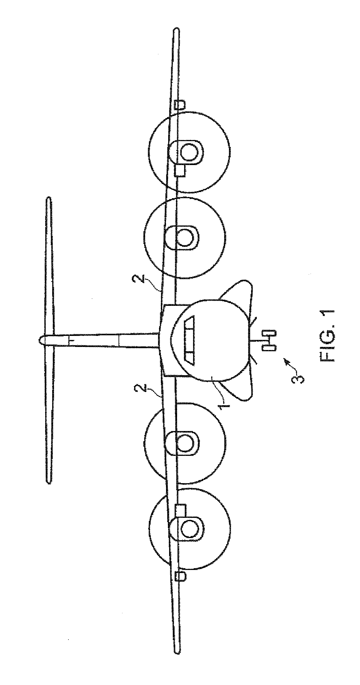
[0019]An aircraft shown in FIG. 1 has an airframe comprising a fuselage 1 and a pair of wings 2. The fuselage 1 has a nose landing gear 3 shown in FIG. 1 in its lowered position.

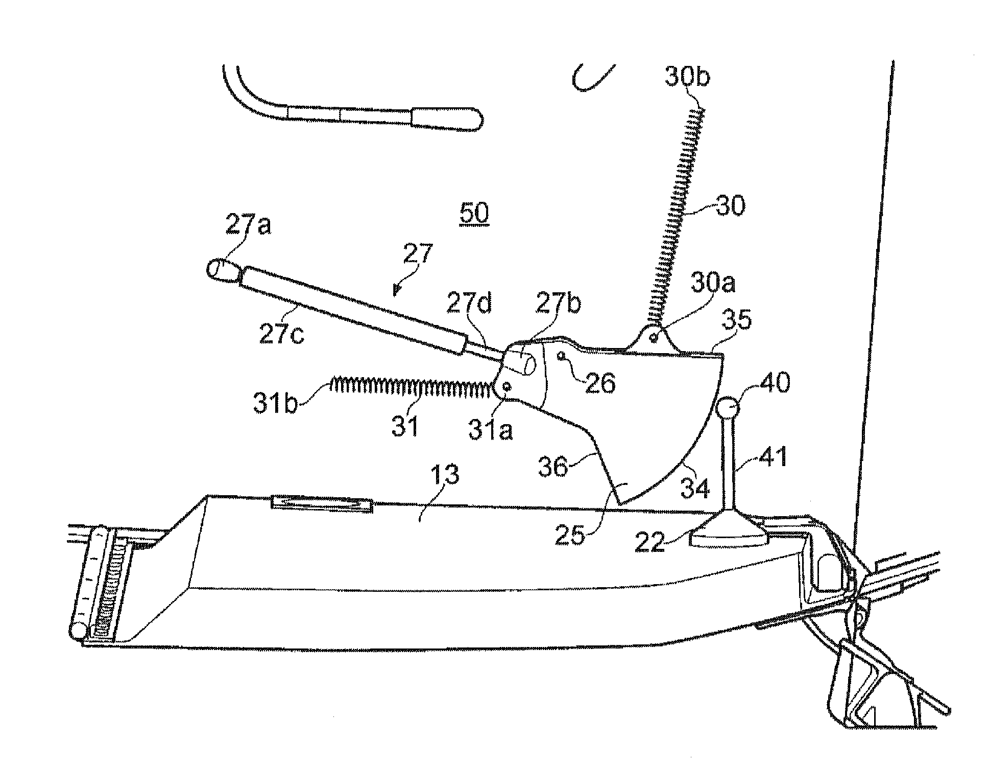
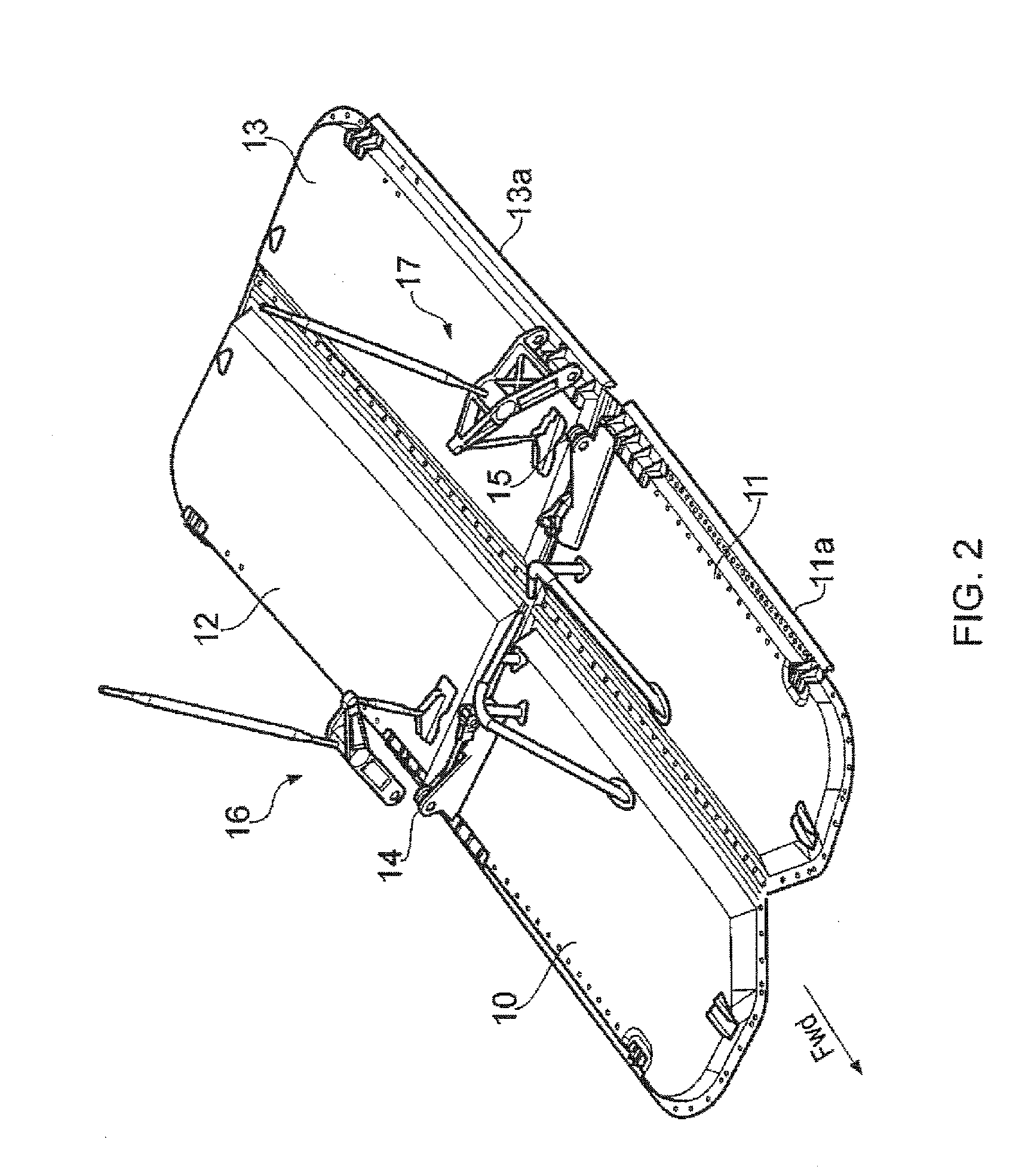
[0020]During cruise of the aircraft the landing gear is housed in a landing gear bay which is closed by four landing gear bay doors 10-13 shown in FIG. 2, each of which is pivotally attached to the fuselage by a hinge 11a, 13a at its outer edge so it can be rotated down from its closed position shown in FIG. 2 to its open position.

[0021]Prior to lowering the landing gear 3 the pair of forward doors 10,11 are opened to about 120° by hydraulic actuators (not shown) attached to fittings 14,15. The landing gear is then lowered, and as it does so the motion of the landing gear causes the rear doors 12,13 to open at the same time via a kinematic linkage mechanism 16,17 attached to each rear door. The forward doors 10,11 are then closed. This sequence is then reversed when the landing gear is raised after takeoff....


PUM


Abstract

The invention provides a damping mechanism which comprises a damper; and a coupling mechanism. The coupling mechanism comprises a coupling member which is pivotally attached to the damper and has a pivot bearing for pivotally connecting the coupling member to a structure when in use; and a fitting which can be engaged with the coupling member to couple the fitting with the damper and disengaged with the coupling member to decouple the fitting from the damper. More, the coupling member has a pair of parallel planar faces which taper outwardly from the pivot bearing to a convex curved edge, an upper edge and a lower edge; and a first and a second recess formed in the convex curved edge, a rib between the first and the second recesses and, a third recess formed in the lower edge.

Description

CROSS-REFERENCE TO RELATED APPLICATION[0001]This application claims priority to European Patent Application No. 12 161 567.8 filed on Mar. 15, 2012, the entire content of which is incorporated by reference herein.FIELD OF THE INVENTION[0002]The present invention relates to a damping mechanism for an aircraft exterior door which is pivotally attached to an airframe, Preferably, although not exclusively, the aircraft exterior door is a landing gear door.BACKGROUND OF THE INVENTION[0003]A known landing gear door installation is described in US 2011 / 0127376 A1. The landing gear compartment is closed by several doors: front doors which open during the descent of the gear, in particular to allow the leg thereof to pass, and close after the exit of the gear so as to preserve the aerodynamic shape of the fuselage of the aircraft; and rear doors which open during the descent of the gear and remain open as long as the gear is down.[0004]As described in FR 2957052 A1, such an arrangement can c...

Claims


Application Information

Patent Timeline
Patent Type & Authority Applications(United States)
IPC IPC(8): B64C25/16
CPCB64C1/1407B64C25/16E05B77/00
Inventor VEERABADRAN, KAROUNEN
Owner AIRBUS OPERATIONS (SAS)
Features
  • R&D
  • Intellectual Property
  • Life Sciences
  • Materials
  • Tech Scout
  • Unparalleled Data Quality
  • Higher Quality Content
  • 60% Fewer Hallucinations
Learn More