Scroll Compressor Counterweight With Axially Distributed Mass

Active Publication Date: 2013-09-26
BITZER KUEHLMASCHINENBAU GMBH
View PDF13 Cites 8 Cited by
  • Summary
  • Abstract
  • Description
  • Claims
  • Application Information

AI Technical Summary

Benefits of technology

This patent describes a new improvement for scroll compressors. These improvements make scroll compressors better than they were before. The technical effect of this innovation is that it can provide more efficient and effective compression of gas, which is important for a variety of applications.

Problems solved by technology

When the mass of the upper counterweight is unevenly distributed, it may cause deflection of the shaft during scroll compressor operation.

Method used


Image

  • Scroll Compressor Counterweight With Axially Distributed Mass
  • Scroll Compressor Counterweight With Axially Distributed Mass
  • Scroll Compressor Counterweight With Axially Distributed Mass

Examples


Embodiment Construction

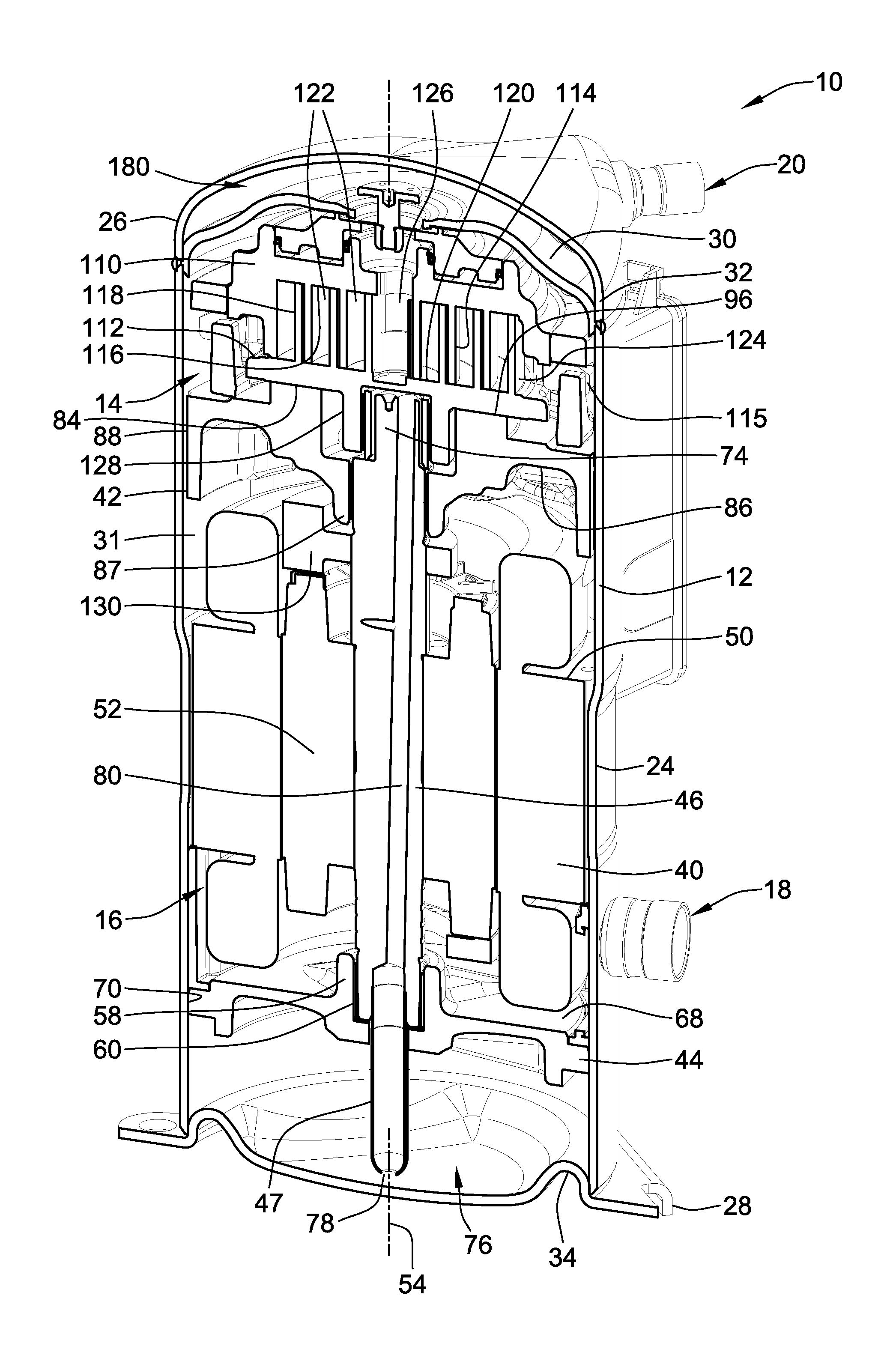
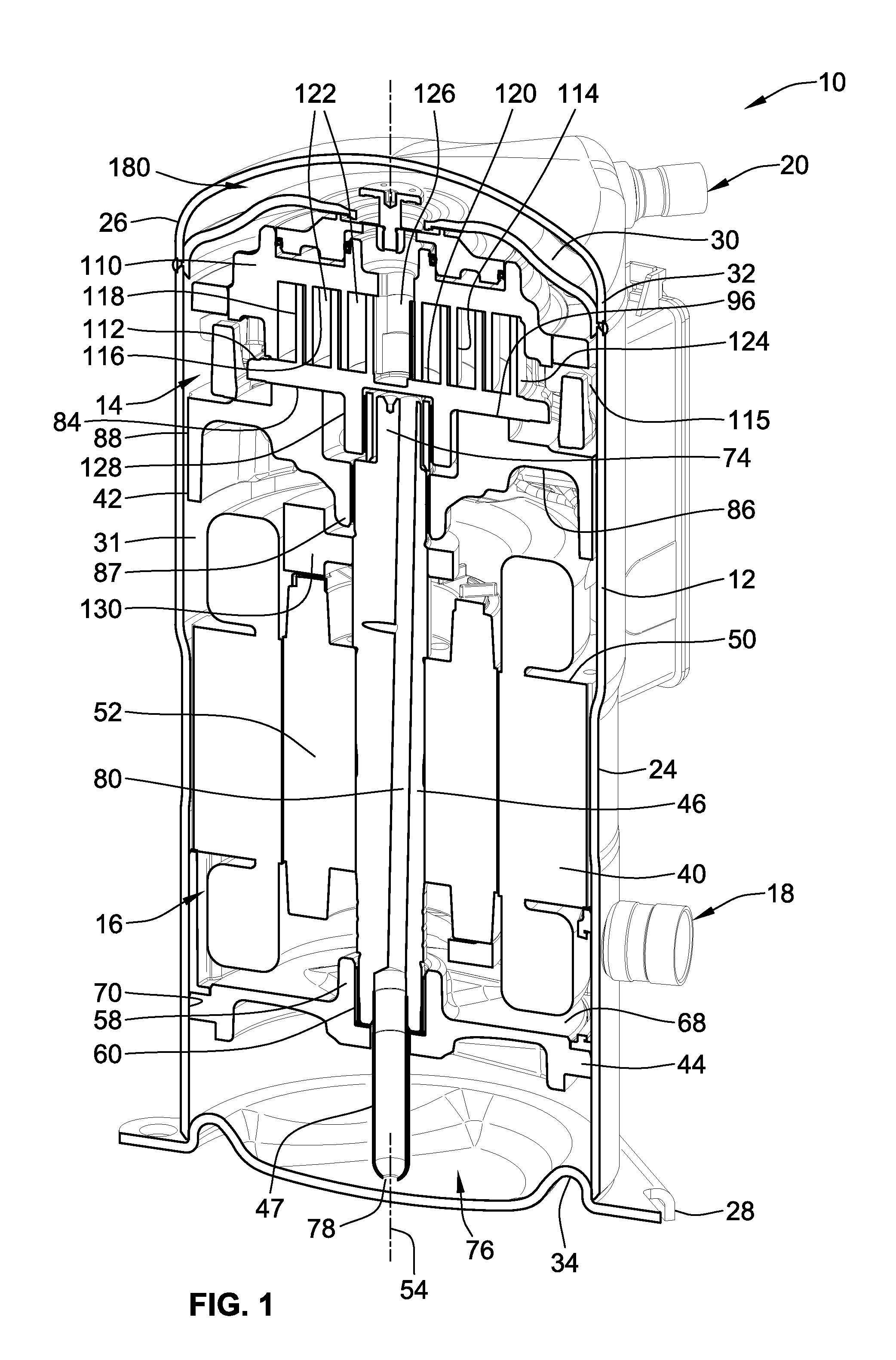
[0026]An embodiment of the present invention is illustrated in the figures as a scroll compressor assembly 10 generally including an outer housing 12 in which a scroll compressor 14 can be driven by a drive unit 16. The scroll compressor assembly 10 may be arranged in a refrigerant circuit for refrigeration, industrial cooling, freezing, air conditioning or other appropriate applications where compressed fluid is desired. Appropriate connection ports provide for connection to a refrigeration circuit and include a refrigerant inlet port 18 and a refrigerant outlet port 20 extending through the outer housing 12. The scroll compressor assembly 10 is operable through operation of the drive unit 16 to operate the scroll compressor 14 and thereby compress an appropriate refrigerant or other fluid that enters the refrigerant inlet port 18 and exits the refrigerant outlet port 20 in a compressed high-pressure state.

[0027]The outer housing for the scroll compressor assembly 10 may take many ...


PUM


Abstract

A scroll compressor includes first and second scroll bodies having respective bases and respective scroll ribs that project from the respective bases such that the scroll ribs mutually engage. The second scroll body is movable relative to the first scroll body for compressing fluid. A drive shaft has a longitudinal axis and an eccentric drive pin configured to engage a drive hub on the second scroll body. A counterweight has a hub portion, and a perimeter portion positioned radially outward from the hub portion. A radial axis divides the counterweight into a first and second regions. The mass of the hub portion in the first region being roughly equal to the mass of the hub portion in the second region, and the mass in the perimeter portion being distributed between the first and second regions such that the center of mass of the counterweight is located along the radial axis.

Description

FIELD OF THE INVENTION[0001]This invention generally relates to scroll compressors for compressing refrigerant.BACKGROUND OF THE INVENTION[0002]A scroll compressor is a certain type of compressor that is used to compress refrigerant for such applications as refrigeration, air conditioning, industrial cooling and freezer applications, and / or other applications where compressed fluid may be used. Such prior scroll compressors are known, for example, as exemplified in U.S. Pat. No. 6,398,530 to Hasemann; U.S. Pat. No. 6,814,551, to Kammhoff et al.; U.S. Pat. No. 6,960,070 to Kammhoff et al.; and U.S. Pat. No. 7,112,046 to Kammhoff et al., all of which are assigned to a Bitzer entity closely related to the present assignee. As the present disclosure pertains to improvements that can be implemented in these or other scroll compressor designs, the entire disclosures of U.S. Pat. Nos. 6,398,530; 7,112,046; 6,814,551; and 6,960,070 are hereby incorporated by reference in their entireties.[0...

Claims


Application Information

Patent Timeline
IPC IPC(8): F04C29/00F04C2/00
CPCF04C23/008F04C29/023F04C2240/807F04C18/0215F04C2240/60F04C29/126
Inventor WANG, XIANGHONGHEUSLER, KENNETH D.
Owner BITZER KUEHLMASCHINENBAU GMBH
Why Eureka
Try Eureka