Corner protector

Inactive Publication Date: 2013-10-03
ARMORED (UK) LTD
View PDF18 Cites 0 Cited by
  • Summary
  • Abstract
  • Description
  • Claims
  • Application Information

AI Technical Summary

Benefits of technology

[0012]Such a side channel arrangement allows the side walls to flex outwardly within the depth of the channels and provides an improved grip and much greater tolerance with respect to the thickness of the

Problems solved by technology

Firstly, the connecting wall provides additional support during normal use, but on the other hand the oute

Method used


Image

  • Corner protector
  • Corner protector
  • Corner protector

Examples


Example

DETAILED DESCRIPTION OF THE DRAWINGS

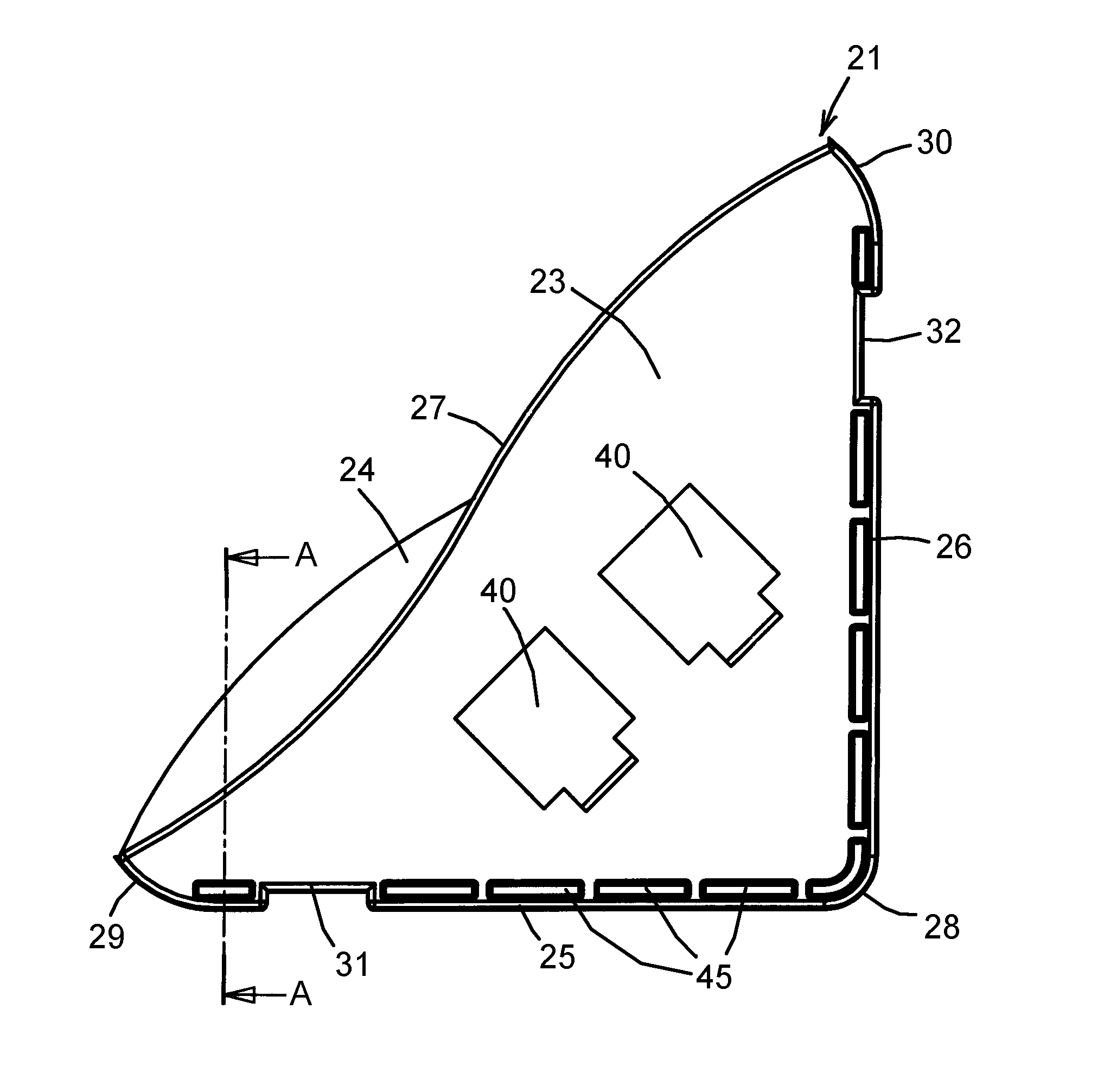
[0021]The corner protector is intended to protect the corners of sheets of glass, metal sheets, furniture, pictures, marble, masonry, etc. Toughened glass is acutely sensitive to light impacts at the corners, for example. As well as protecting a corner from impacts during handling, transportation and storage, the device also reduces the risk of damage to floors, walls, ceilings, furniture etc. caused by accidental contact with such corners during handling, and may also protect transport vehicles from damage.

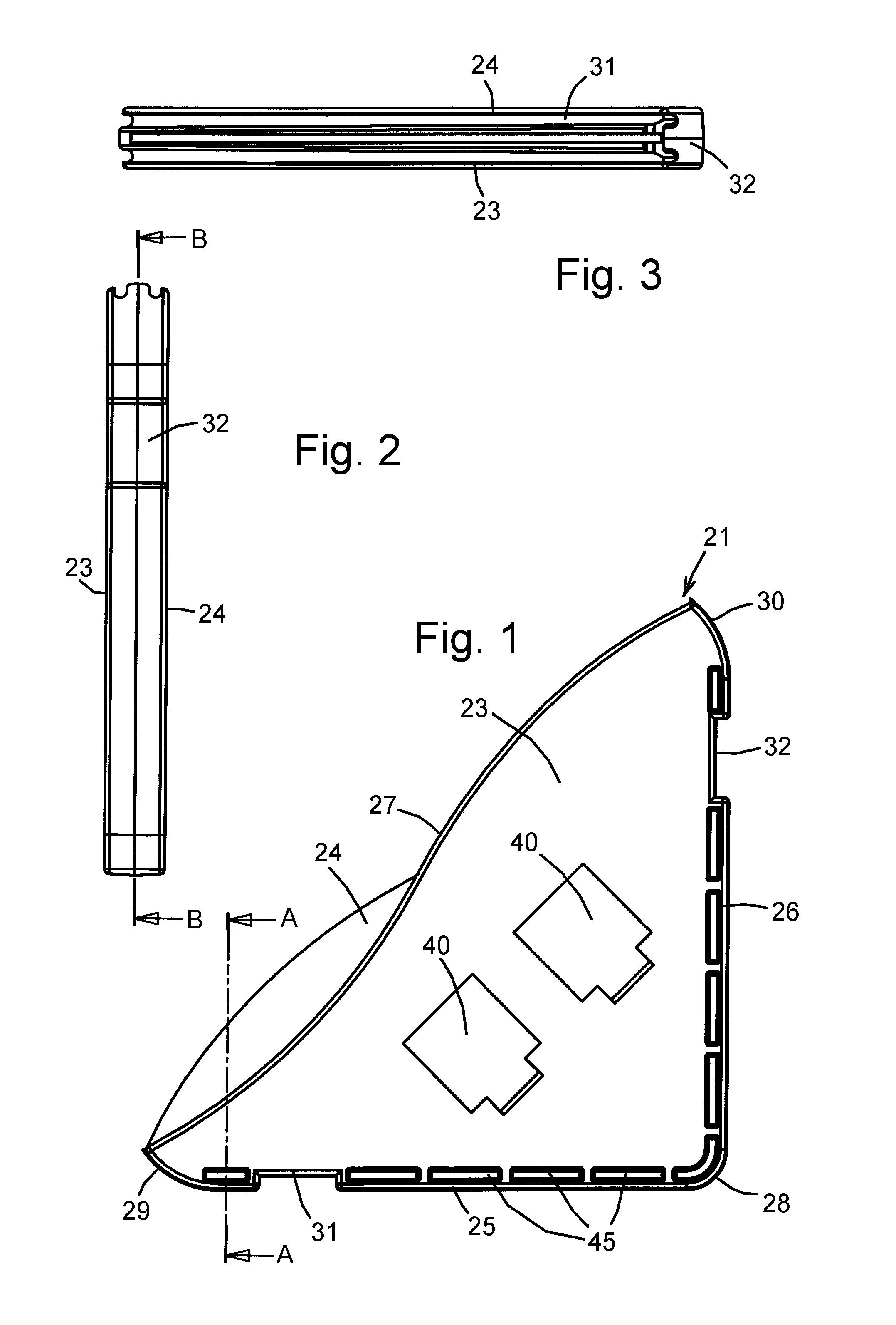
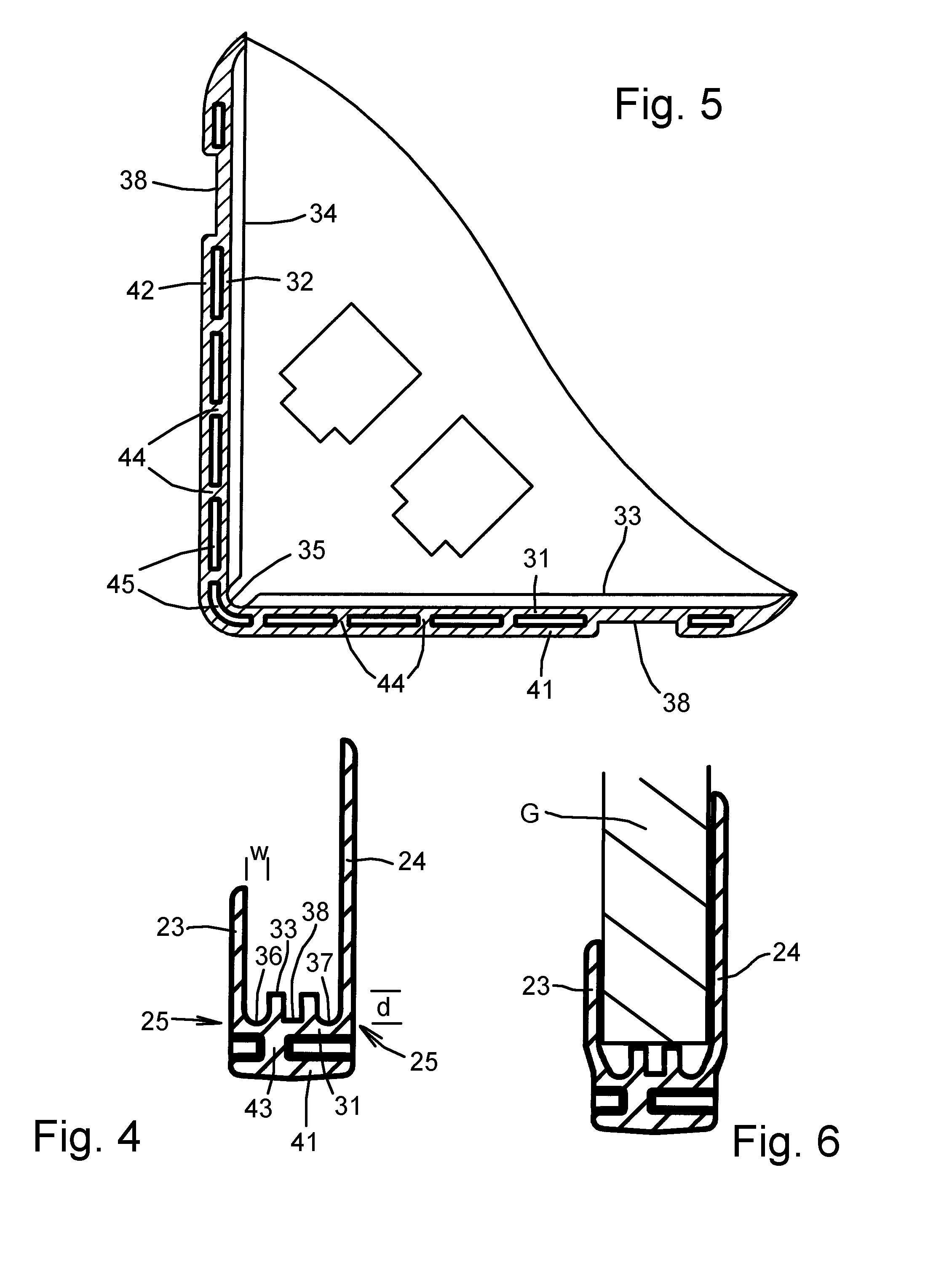
[0022]Referring to FIGS. 1 to 3, the corner protector comprises an injection moulded plastic component 21 having two substantially parallel side walls 23 and 24 connected by a pair of mutually perpendicular bridging walls 31 and 32. The side walls 23 and 24 are both of generally triangular shape, having a pair of mutually perpendicular edges 25 and 26 joined by a curved third edge 27. The junction between the perpendicular edges 25 and 26 is cu...


PUM


Abstract

A pair of opposing side walls (23, 24) are joined by substantially perpendicular bridging walls (31, 32) provided with an outer wall (41, 42) which is spaced from the bridging wall by a longitudinal connecting wall (43) and spaced transverse connecting walls (44). The outer wall (41, 42) is intended to be crushed under the force of a heavy impact. The longitudinal wall (43) is offset from the centre line so that even in the event of a square-on impact the outer wall can still deform inwardly on one side. The inner faces of the bridging walls (31, 32) include a longitudinally-extending support surface bounded by side channels (36, 37) having side faces which are coplanar with the inner faces of the side walls (23, 24). Such an arrangement allows the side walls to flex outwardly within the depth of the channels and provides an improved grip and improved tolerance with respect to the thickness of the protected article.

Description

TECHNICAL FIELD OF THE INVENTION[0001]This invention relates to an improved form of the corner protector disclosed in WO 2007 045 822 A1.BACKGROUND[0002]The corner protector disclosed in the abovementioned document is moulded from plastics material and has a pair of opposing side walls connected by a pair of substantially perpendicular bridging walls. In order to reduce the risk of damage to a protected article, internal channels extend along the junction between the side walls and the bridging walls. However, damage may still occur in the event of a very heavy impact such as may occur when a sheet of glass or marble is dropped onto a protected corner. Furthermore, the earlier corner protector may be difficult to fit due to low tolerance in the dimensions of the protected article combined with a tendency to distortion during cooling of the plastic.[0003]The present invention seeks to provide an improved form of corner protector which can be fitted to articles with a wider thickness ...

Claims


Application Information

Patent Timeline
IPC IPC(8): B65D81/05
CPCB65D81/054B65D81/057
Inventor MURDOCH, THOMAS
Owner ARMORED (UK) LTD
Why Eureka
Try Eureka