
Gas Treatment Apparatus with Surrounding Spray Curtains

a technology of gas treatment apparatus and spray curtain, which is applied in the direction of lighting and heating apparatus, combustion types, coatings, etc., can solve the problems of unfavorable gas distribution, interference with efficient operation or uniform deposition, and unwanted deposition

Inactive Publication Date: 2013-10-17
HERMES EPITEK
View PDF12 Cites 334 Cited by
  • Summary
  • Abstract
  • Description
  • Claims
  • Application Information

AI Technical Summary

Benefits of technology

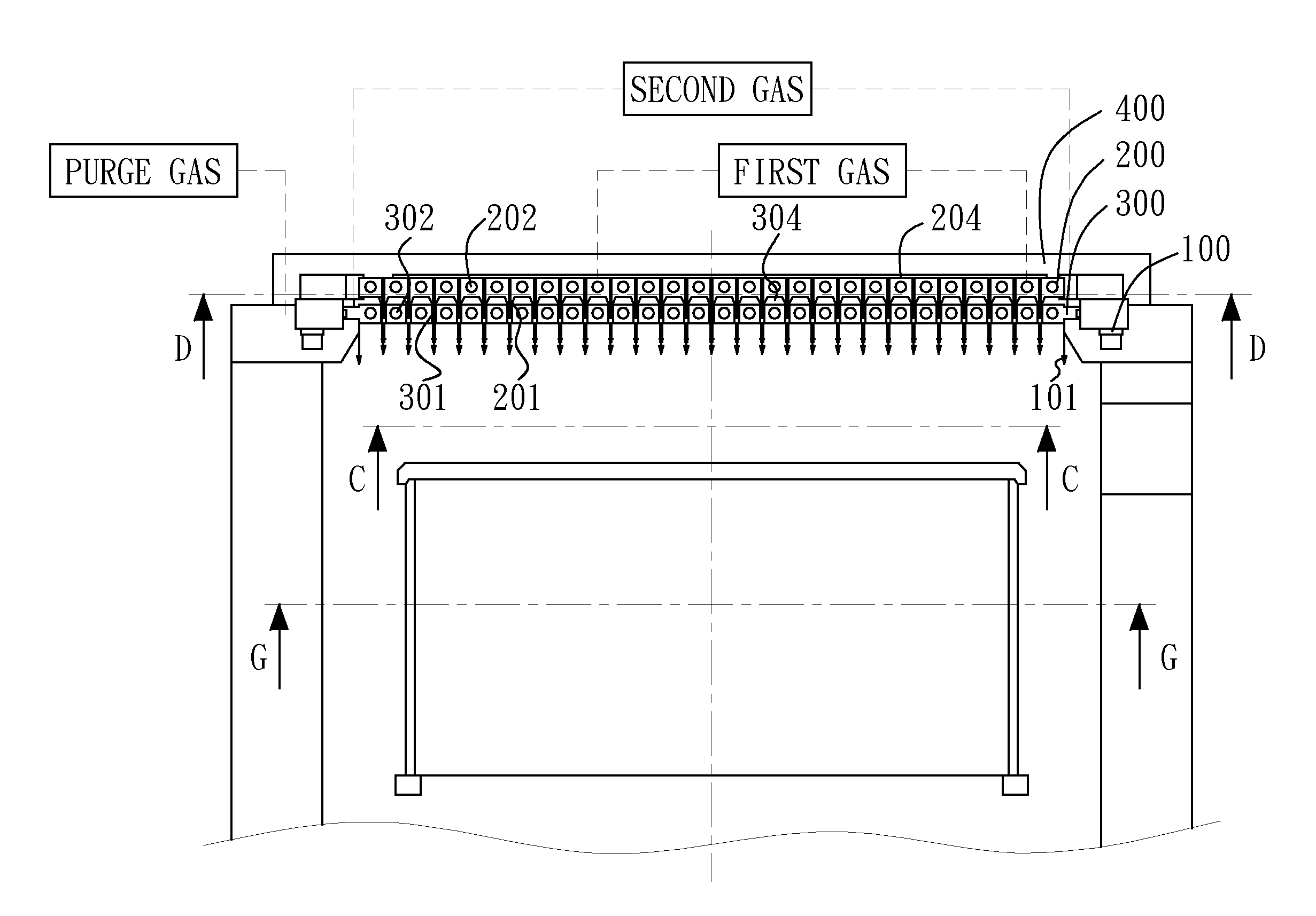
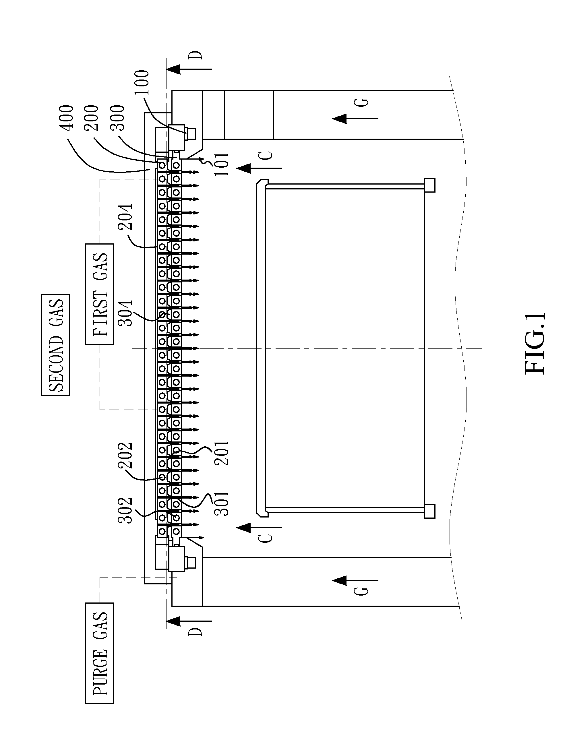
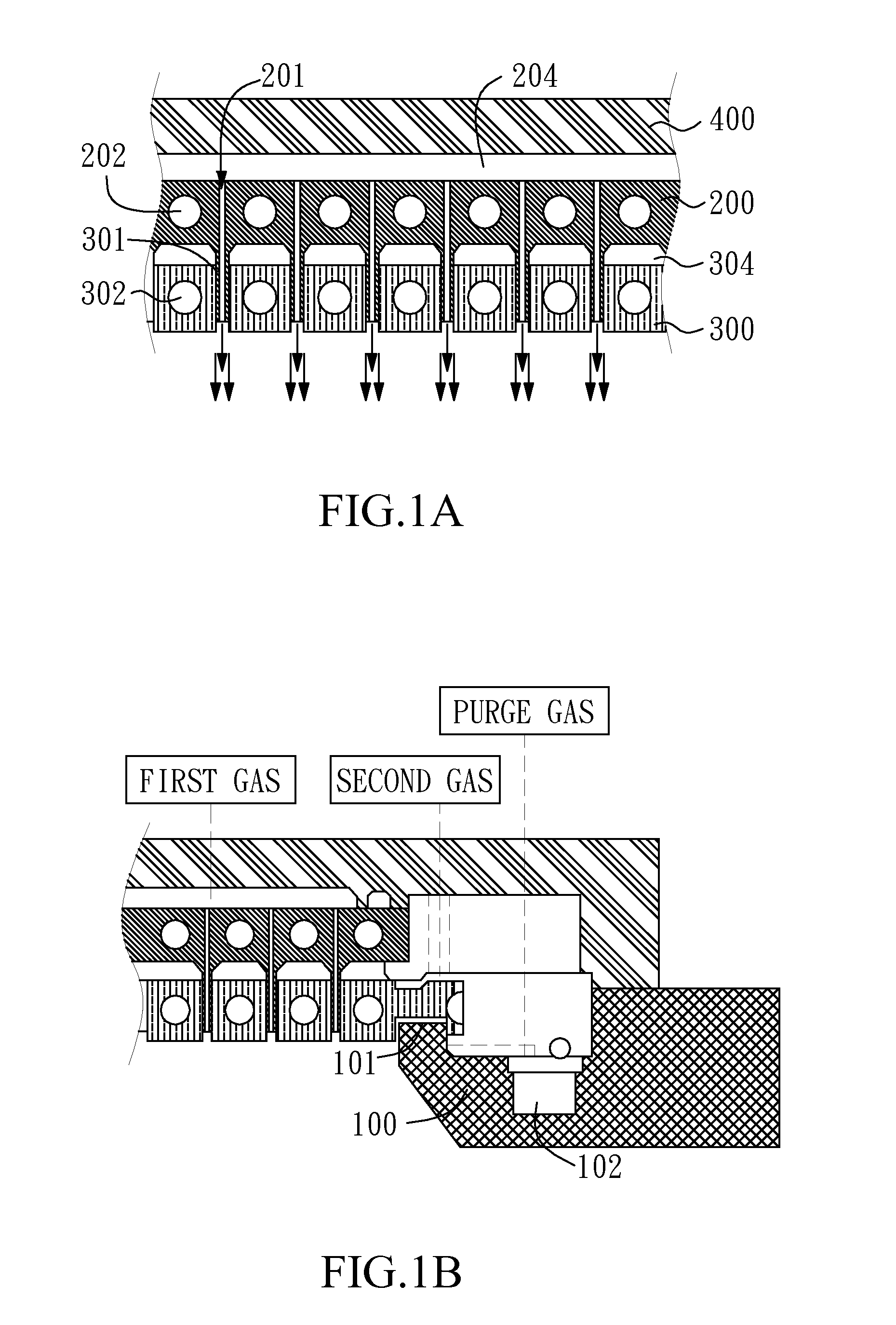
The invention provides a deposition system with a gas treatment apparatus. The gas treatment apparatus includes an exterior circular gas spray portion with a first plenum, first gas channels, and first heat exchange fluid conduits. The upper gas spray portion has a second plenum, second gas channels, and second heat exchange fluid conduits. The lower gas spray portion has a first gas channel and second heat exchange fluid conduits. The gas treatment apparatus improves the quality and efficiency of gas deposition in a chamber.

Problems solved by technology

However, many existing showerheads have problems that may interfere with efficient operation or uniform deposition due to the design of gas channel.
For example, gas spray in existing showerhead may induce significant space in the chamber without effective gas flow from the gas vents of the showerhead to the semiconductor wafer resulting in a non-uniform distribution of gases.
The non-uniform distribution of gases may cause unwanted deposition or non-uniform deposition.
Such unwanted deposition consumes reactants and decreases the efficiency and the non-uniform deposition would further reduce the throughput of the process.
Thus, many current systems require frequent cleaning of the reactor, which further reduces productivity.
Some existing showerheads also have problems of efficient operation or uniform deposition due to the cooling design.
Owing to the inefficient cooling design, the formation of condensates on the showerhead as well as gas phase particle formation and the production of undesirable precursor reactant products may adversely affect the composition of the thin film deposited on the semiconductor wafers.
In U.S. Patent Application No. 2007 / 0163440, the gas separation type showerhead which separately provides two different gases without cooling design might cause reaction and undesirable deposition on the holes and vents and form obstacles to the gas flows.
In U.S. Pat. No. 7,976,631, each the heat exchanging channel of the showerhead is arranged only adjacent to one side of two adjacent gas channels and such cooling design obviously cannot provide uniform heat exchange.
The heat exchanging channel is also arranged only adjacent to one side of two adjacent gas channels and this inefficient cooling design would result in the formation of condensates on the showerhead as well as gas phase particle formation.

Method used


Image

  • Gas Treatment Apparatus with Surrounding Spray Curtains
  • Gas Treatment Apparatus with Surrounding Spray Curtains
  • Gas Treatment Apparatus with Surrounding Spray Curtains

Examples


Embodiment Construction

[0021]Reference will now be made in detail to specific embodiments of the invention. Examples of these embodiments are illustrated in accompanying drawings. While the invention will be described in conjunction with these specific embodiments, it will be understood that it is not intended to limit the invention to these embodiments. On the contrary, it is intended to cover alternatives, modifications, and equivalents as may be included within the spirit and scope of the invention as defined by the appended claims. In the following description, numerous specific details are set forth in order to provide a thorough understanding of the present invention. The present invention may be practiced without some or all of these specific details. In other instances, well known process operations and elements are not described in detail in order not to unnecessarily obscure the present invention.

[0022]One embodiment of the invention generally provides a deposition system with a gas treatment ap...


PUM

PropertyMeasurementUnit
Volumeaaaaaaaaaa
Shapeaaaaaaaaaa

Abstract

The invention provides a gas treatment apparatus comprising an exterior circular gas spray portion, an upper gas spray portion, a lower gas spray portion and a cover on the exterior circular gas spray portion and the upper gas spray portion. The upper gas spray portion has a plurality of first gas channels and a plurality of first heat exchange fluid conduits, each the first gas channel is arranged interlaced with each the first heat exchange fluid conduit. The lower gas spray portion comprises a plurality of second gas channels and a plurality of second heat exchange fluid conduits, wherein the second plenum is located under the first heat exchange fluid conduits and above the second heat exchange fluid conduits, each the second gas channel is arranged interlaced with each the second heat exchange fluid conduit, and each the second gas channel surrounds each the first gas channel.

Description

BACKGROUND OF THE INVENTION[0001]1. Field of the Invention[0002]The present invention generally relates to a gas treatment apparatus, and more particularly to a gas treatment apparatus with surrounding spray curtains.[0003]2. Description of Related Art[0004]Thin film deposition processes such as chemical vapor deposition (CVD) processes are carried out inside a chamber provided with a showerhead in semiconductor manufacturing processes. The semiconductor wafers are places on a wafer carrier with a heating function and the showerhead sprays reaction gases required for the processes into the chamber and over the semiconductor wafers on the wafer carrier. When reaction gases such as precursor gases containing materials to be deposited are sprayed onto the semiconductor wafers through the showerhead in a gas state, a chemical reaction occurs within the chamber, and thus the thin film is formed. During the chemical reaction, a high temperature must be maintained inside the chamber for th...

Claims


Application Information

Patent Timeline
IPC IPC(8): C23C16/458B05B1/24C23C16/455
CPCC23C16/45565C23C16/4557C23C16/45519C23C16/45574C23C16/45572
Inventor CHENG, JUI-SHENGHAN, TSUNG-HSUN
Owner HERMES EPITEK
Learn More