Unlock instant, AI-driven research and patent intelligence for your innovation.
Glove for gripping small object
Inactive Publication Date: 2013-11-07
JOINCROSS
View PDF25 Cites 11 Cited by
Summary
Abstract
Description
Claims
Application Information
AI Technical Summary
This helps you quickly interpret patents by identifying the three key elements:
Problems solved by technology
Method used
Benefits of technology
Benefits of technology
The patent allows users to control a device with a gloved touch. This allows for easy use without having to remove the glove.
Problems solved by technology
However, when a user works while wearing the glove, it is difficult for the user to grip small instruments, such as, a needle, a pin, a nail, a screw, and so on.
Therefore, the user should take off the glove and grip the small objects with bare hands, and thus, it is inconvenient.
Further, if the grip of the small object is difficult with even bare hands due to the size of the small object, an additional instrument should be prepared.
Thus, signal cannot be provided to a touch panel of a resistance type and a capacitance type when the user wears the glove.
Secondly, when the finger is inserted to a space of a glove finger portion, an extra space is formed between the glove and the hand because the glove is larger than the finger.
When the end portion of the glove is in contact with the object, the extra space is folded and creases are generated, and thus, the grip of the small object is disturbed.
Thirdly, the human hand has nails.
Fourthly, in order to grip the small object that the maintenance of the gripped contact point is impossible (such as, the object has a sphere shape or a round bar), the small object is raised through gripping central lower portions of the object are gripped by the nails, and then, the small object is settled between the nails and finger print portions.
However, in the state that the glove is worn, the pulling the small object upward or the settlement between the nail and the fingerprint portion are impossible.
Method used
Image
Click on the blue label to locate the original text in one second.
Reading with bidirectional positioning of images and text.
Examples
first embodiment
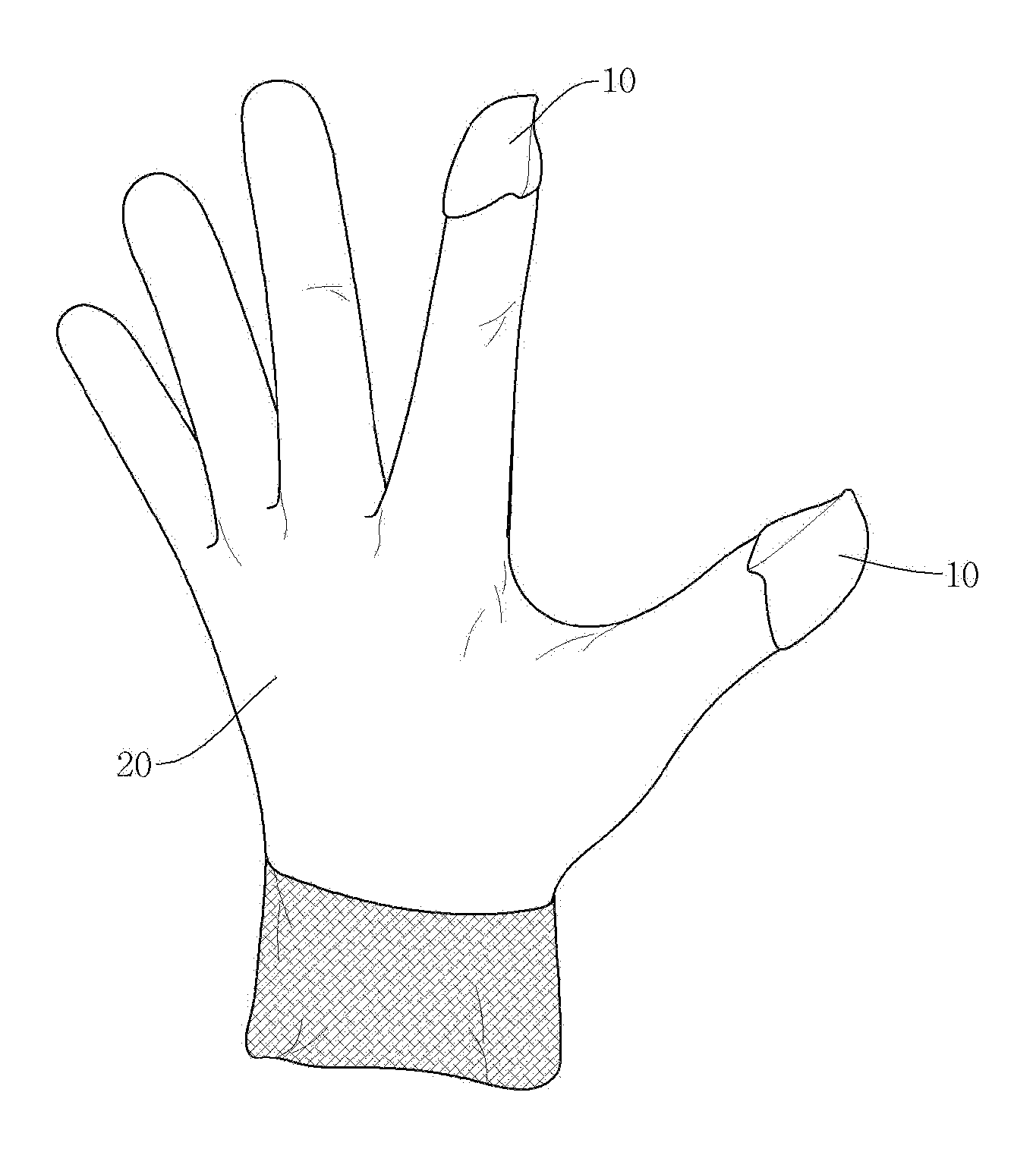
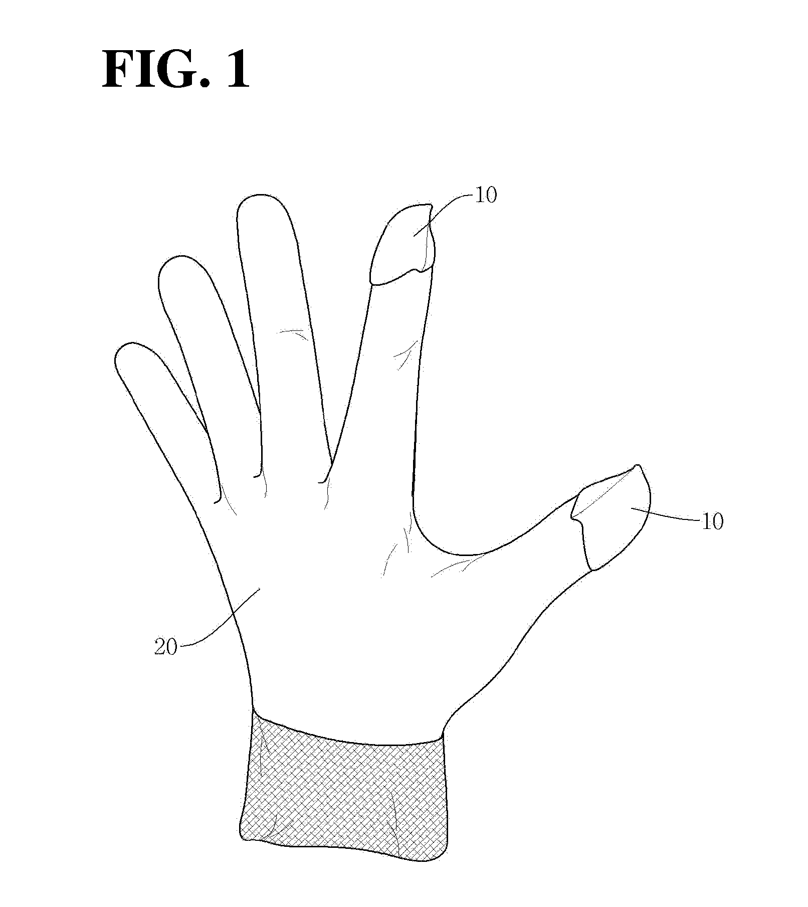
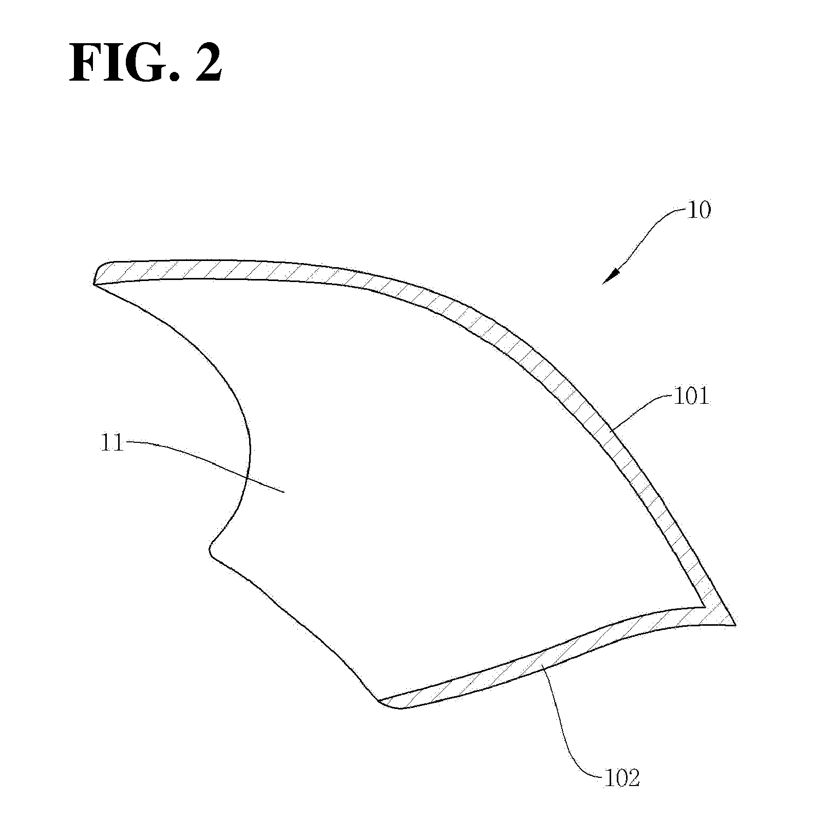
[0039]Hereinafter, with reference to accompanying drawings, examples of the present invention will be described in detail. For convenience, like reference numerals refer to like elements throughout. FIG. 1 is a perspective view of a glove for gripping a small object according to the present invention, and FIG. 2 is a cross-sectional view taken along line I-I′ of FIG. 1.
[0040]With reference to FIG. 1 and FIG. 2, a glove for gripping a small object according to the present embodiment includes a glove main body 20 including a finger potion for covering a finger, and a thimble portion 10.
[0041]The thimble portion 10 is formed at an end portion of the finger portion of the glove. The thimble portion 10 includes a first layer 101 facing the back of a hand and a second layer 102 being opposite to the first layer 101. Front sides of the first layer 101 and the second layer 102 are adhered to each other and form a structure where the finger is inserted. In this instance, the thimble portion ...
second embodiment
[0057]FIG. 5 is a structural view of a glove for gripping a small object according to the present invention.
[0058]In the embodiment, at least a part of a portion where a second layer 102 of a forefinger thimble portion 10-2 is mounted has a hole 201, and a finger of a user is in direct contact with the forefinger thimble portion 10. In this instance, the forefinger thimble portion includes a conductive resin, and thus, a current of the finger of the user is transferred to the touch screen through the forefinger thimble portion, thereby generating the capacitance change of the touch screen.
[0059]In this instance, widely known moldable conductive resin may be used the conductive resin. A material that a conductive metal and resin are mixed is generally used. For example, iron, cupper, nickel, and so on may be used for the metal, and PPE, PC, and so on may be used for the resin.
third embodiment
[0060]FIG. 6 is a structural view of a glove for gripping a small object according to the present invention.
[0061]In the embodiment, a stylus pen is mounted on the first layer 102. That is, the stylus pen is mounted in the first layer 102. The stylus pen may be integrated with the thimble portion during an injection molding, or may be detachable to the thimble portion.
[0062]The stylus pen includes a battery 302, and a conductive tip 301 for transferring the current of the battery. Also, a connection element for connecting the battery 302 and the conductive tip 301 may be further included.
[0063]The battery 302 is a small size battery having a size being able to be included in the first layer. The conductive tip 301 has a stick shape extending in the finger direction. Also, the front end portion of the conductive tip 301 may be preferably consistent with or aligned with the front end portion of the thimble portion.
[0064]FIG. 7 is a structural view of a glove for gripping a small objec...
PUM
Abstract
A glove for gripping a small object is disclosed. A glove for gripping a small object comprises: a glove main body comprising a finger portion for covering a finger; and a thimble portion comprising a thumb thimble portion and a forefinger thimble portion. Each of the thumb thimble portion and the forefinger thimble portion comprises a first layer facing the back of a hand and a second layer being opposite to the first layer. A front side of the first layer and a front side of the second layer are adhered to each other and form an edge line. A rear side of the thimble portion is open to be mounted on the finger portion. A right-and-left center line of an outer surface of the first layer of the thumb thimble portion and a right-and-left center line of an outer surface of the first layer of the forefinger thimble portion are aligned with each other within an error margin of about 0 mm to about 0.5 mm, when a user wear the glove and aligns a front end portion of the thumb thimble portion with a front end portion of the forefinger thimble portion.
Description
CROSS-REFERENCE TO RELATED APPLICATIONS[0001]The present application is a continuation of International Application No. PCT / KR2011 / 009460 filed Dec. 8, 2011, which claims priority to Korean Application No. 10-2010-0135219 filed Dec. 27, 2010, which applications are incorporated herein by reference.TECHNICAL FIELD[0002]The present invention relates to a glove for gripping a small object, and more particularly, to a glove for gripping a small object having a structure of a thimble portion and a forefinger portion being able to easily grip the small object.BACKGROUND ART[0003]A conventional glove is used for protecting a hand or for maintaining temperature of the hand regardless of the outside temperature. Recently, a function of a glove is being expanded from the protection of the hand. Thus, various gloves such as a cut resistant glove, a non-slipping glove, a heat resistant glove, a winter glove, an acid-resistant glove, a flame resistant glove, a vibration isolation glove, a glove ...
Claims
Application Information
Patent Timeline
Application Date:The date an application was filed.
Publication Date:The date a patent or application was officially published.
First Publication Date:The earliest publication date of a patent with the same application number.
Issue Date:Publication date of the patent grant document.
PCT Entry Date:The Entry date of PCT National Phase.
Estimated Expiry Date:The statutory expiry date of a patent right according to the Patent Law, and it is the longest term of protection that the patent right can achieve without the termination of the patent right due to other reasons(Term extension factor has been taken into account ).
Invalid Date:Actual expiry date is based on effective date or publication date of legal transaction data of invalid patent.
