

Glass base material elongating method and glass base material elongating apparatus
a technology of glass base material and elongating apparatus, which is applied in the direction of lighting and heating apparatus, instruments, furniture, etc., can solve problems such as degrading yield or productivity
- Summary
- Abstract
- Description
- Claims
- Application Information
AI Technical Summary
Benefits of technology
Problems solved by technology
Method used
Image

Examples
first embodiment
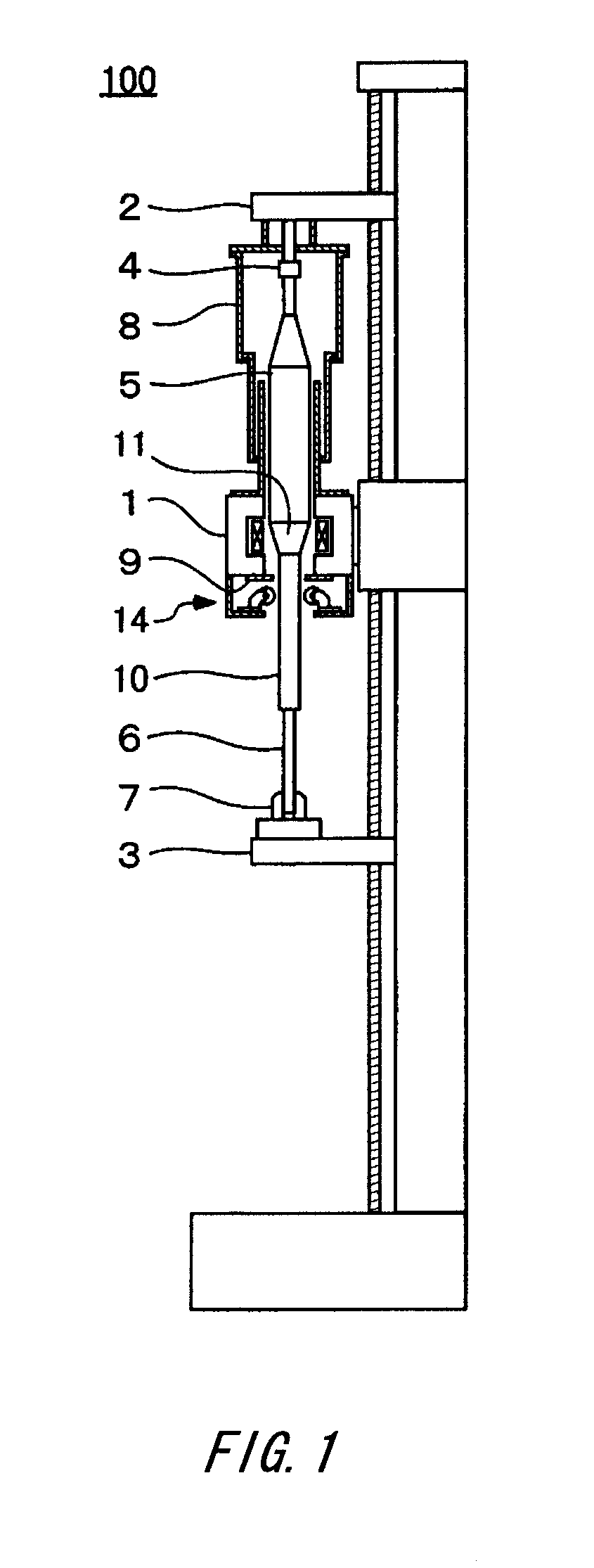
[0023]FIG. 1 is a schematic diagram showing a structure of a glass base material elongating apparatus 100. The elongating apparatus 100 includes a feeding mechanism 2, a heating furnace 1, an alignment guiding device 14 and a pulling mechanism 3, all of which are provided in this order from above in the direction of the gravitational force.
[0024]A glass base material5 is hung via a hanging connecting part 4 in the feeding mechanism 2. A lower part of the glass base material 5 is connected to the pulling mechanism 3 via a pulling dummy 6 and a pulling chuck 7. The pulling chuck 7 has a load meter that measures loads that are applied vertically upward and downward.
[0025]The heating furnace 1 has, for example, a carbon heater. For the purpose of preventing wear due to oxidation, inert gas such as nitrogen and argon is introduced into the heating furnace 1. Also, for the purpose of preventing the outside air from entering into the heating furnace 1, a top chamber 8 and a furnace exit ga...
example 2
[0054]FIG. 10 shows an initial state of operation of another alignment guiding device 25. FIG. 10 is illustrated as seen from the same perspective as that of FIG. 4, the same elements as those in FIG. 4 are provided with the same reference numerals, and explanation is not repeated.
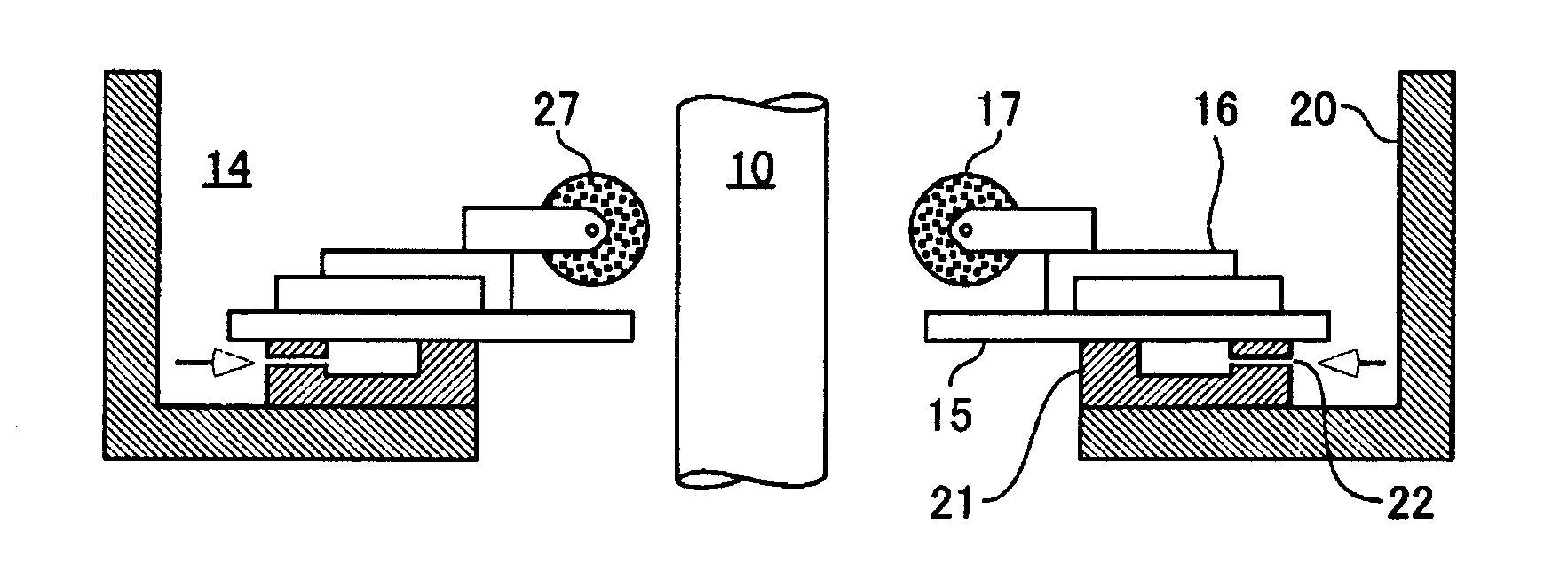
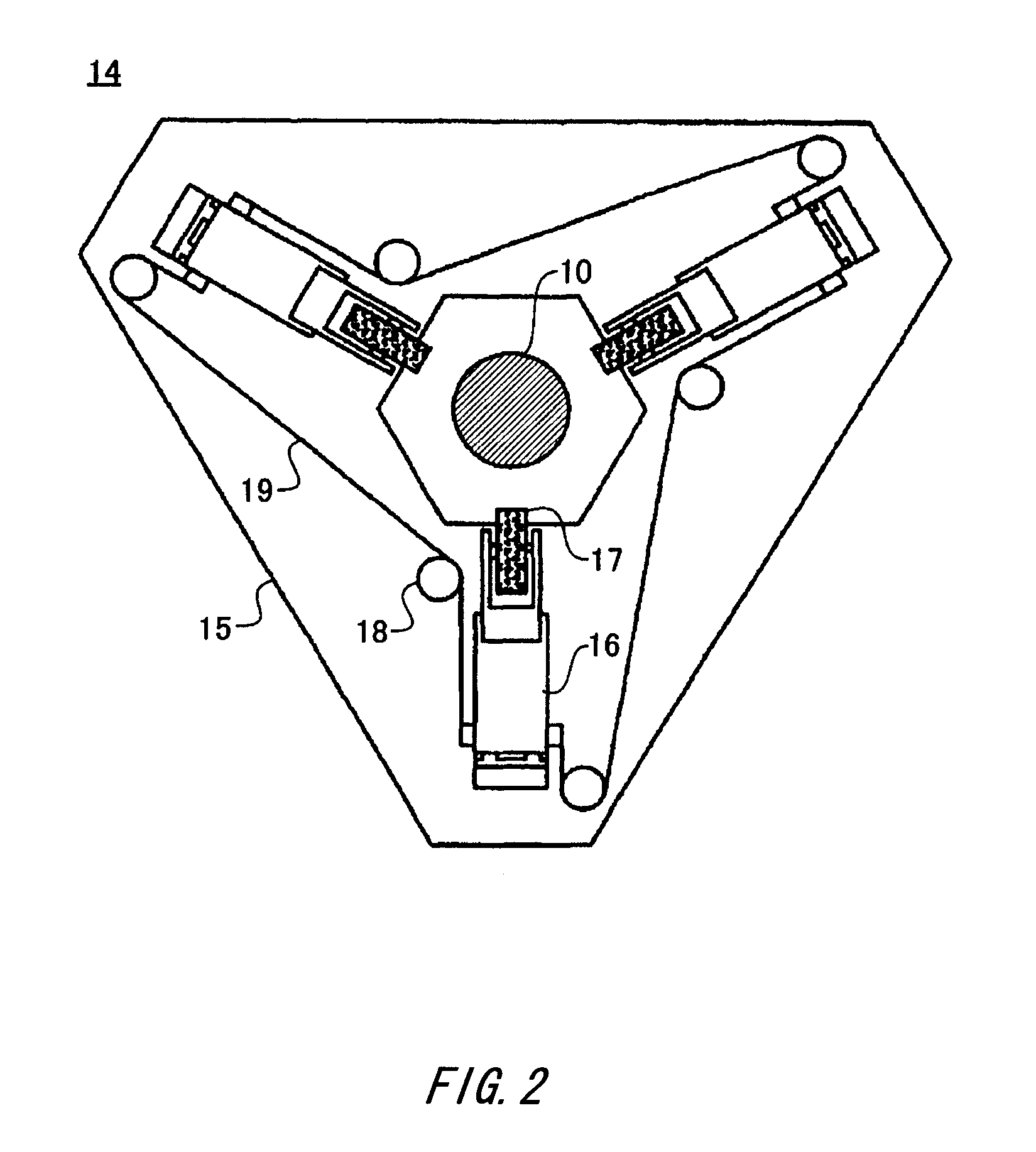
[0055]The alignment guiding device 25 is provided with a horizontal position adjusting mechanism 23 and a rod position identifying device 24. The horizontal position adjusting mechanism 23 is mounted on a mount 20. A base plate 15 is mounted on the horizontal position adjusting mechanism 23. A slide table 16 and a carbon guiding roller 17 are attached on the base plate 15. The horizontal position adjusting mechanism 23 may be, for example, an electrically-driven XY table.
[0056]The rod position identifying device 24 is fixed on the mount 20, and measures the horizontal position of a glass rod 10. That is, the rod position identifying device 24 consists of two pair of devices that can measure the horizontal ...
experiment example 1
[0061]A glass base material 5 with the length of a straight barrel part of approximately 2000 mm and the outer diameter of approximately 180 mm was elongated to form a glass rod 10 with the length of approximately 2530 mm and the outer diameter of 160 mm, by using the elongating apparatus 100 provided with the alignment guiding device 14. When a downward load started to be applied to the pulling mechanism in the last half of elongation, the slide tables 16 were operated synchronously, the guiding center of the alignment guiding device 14 was aligned with the axis of the glass rod 10, and the aligning mechanism was fixed at this position.
[0062]The degree of bending (BOW values) of the twenty thus-elongated glass rods 10 was measured, and the result showed the average value of 0.55 mm / m, and the maximum value of 1.02 mm / m. FIG. 9 shows a BOW value measurement method that was used. BOW values are obtained by dividing maximum widths G [mm] of whirling that occurred when the glass rods w...
PUM
| Property | Measurement | Unit |
|---|---|---|
| outer diameter | aaaaa | aaaaa |
| outer diameter | aaaaa | aaaaa |
| length | aaaaa | aaaaa |
Abstract
Description
Claims
Application Information