

Sound reflector and electronic device with speaker, including sound reflector
- Summary
- Abstract
- Description
- Claims
- Application Information
AI Technical Summary
Benefits of technology
Problems solved by technology
Method used
Image

Examples
Embodiment Construction
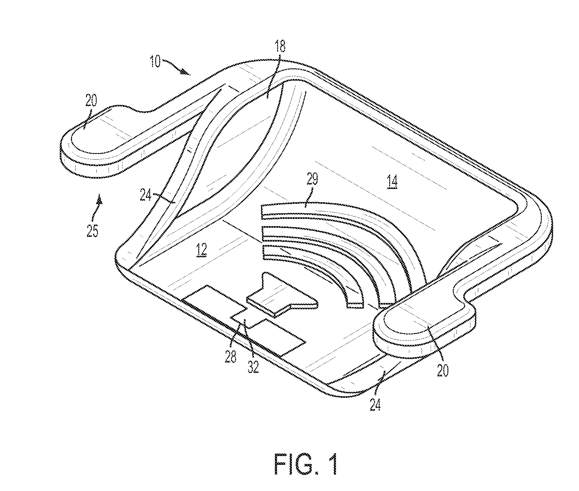
[0026]FIGS. 1-7 illustrate a preferred embodiment of a reflector 10 according to the invention. This reflector is made essentially of one piece of plastic, such as polypropylene, polyethylene, or PVC, although other plastic materials, such as polycarbonate compounds, or more resilient, flexible materials, such as rubber or silicone rubber, may be used.
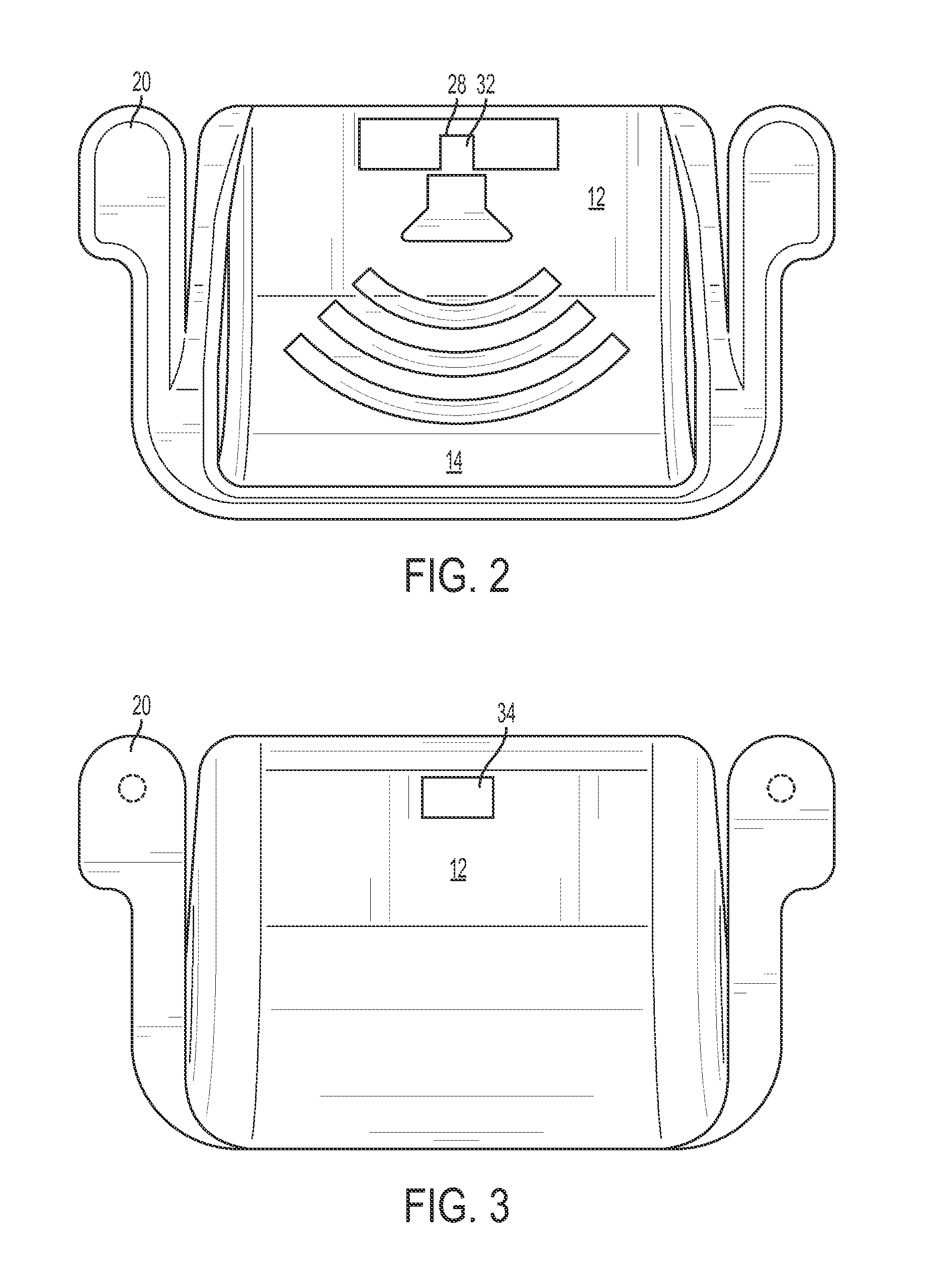
[0027]Reflector 10 has an interior part that includes a flat portion 12 and an arcuate concave portion 14, located between two side members 18. Two tabs, or legs, 20 extend in a direction that is parallel to the plane of flat portion 12 and are spaced from flat portion 12 in a direction perpendicular to the plane of flat portion 12.
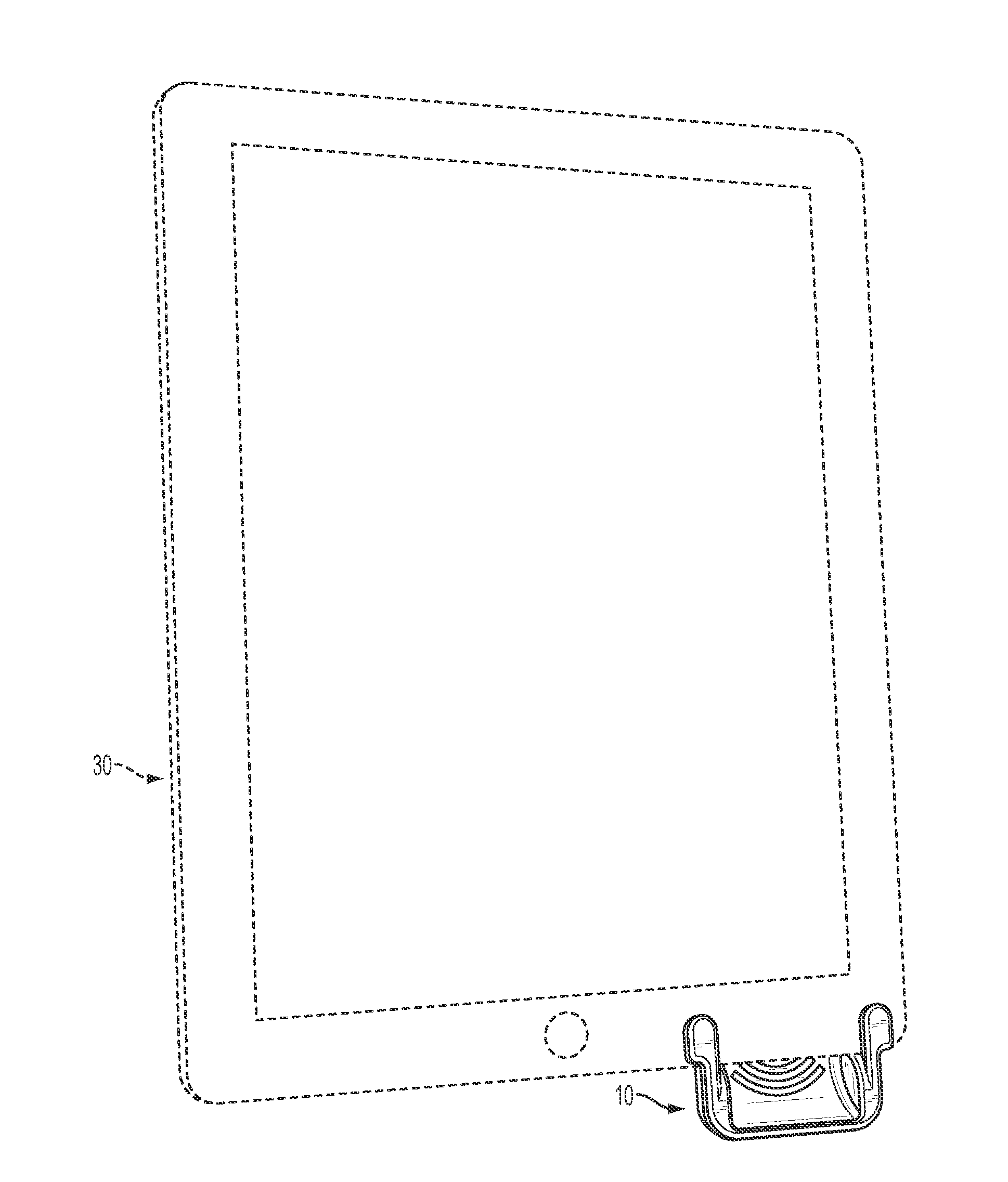
[0028]Side members 18 have concave edges 24 that cooperate with tabs 20 to create recesses 25 that allow reflector 10 to be mounted on an electronic device 30 such as an iPad 2®, as shown in FIG. 8. Side members 18 form solid walls that each extend from a respective edge 24 to bottom portion 12 and concave p...
PUM
 Abstract
Description
Claims
Application Information