Active vibration isolation system

a technology of active vibration and isolation system, which is applied in the direction of shock absorbers, program control, instruments, etc., can solve the problems of compromising efficiency, difficult to suppress vibration at low frequencies, and high cost of actuator types

Active Publication Date: 2013-12-12
TECHN MFG
View PDF3 Cites 33 Cited by
  • Summary
  • Abstract
  • Description
  • Claims
  • Application Information

AI Technical Summary

Benefits of technology

[0008]In a further embodiment, a passive damping element is included in parallel to the support spring, between the payload and the intermediate mass. The passive damping element can act to direct dynamic forces from the payload to the stability point where such forces can be dampened. The support spring, along with the passive damping element, can act to elastically decouple the supported payload from the intermediate mass.
[0009]In another embodiment, the active vibration damping system includes a plurality of actuators attached between the intermediate mass and base or ground. Sensors associated with the actuators can be attached to the intermediate mass and the orientation of the actuators, in conjunction with the sensors, is such that the system may dampen vibration from the ground to the intermediate mass along two or three axes.

Problems solved by technology

Passive isolators, such as dampers and absorbers, are mechanical solutions that, while effective, have difficulty suppressing vibrations at low frequencies.
This type of actuator can be quite expensive; therefore, to reduce the strain and wear on the actuator, some systems combine the actuator with other passive support elements, such as an offload or support spring, to bear a portion of the static weight.
However, as disclosed in U.S. Patent Application Publication No. 2010 / 0030384, it is generally accepted that the extent to which an offload spring may reduce the burden on the actuator by bearing a portion of the static weight is limited because of the risk that the offload spring would compromise the efficiency of the vibration isolation system.
In particular, because the support springs extend from the ground, vibration at frequencies below the resonance frequency of the springs may transfer from the ground through the springs resulting in compromised performance of the active dampening portion of the vibration isolation system.

Method used


Image

  • Active vibration isolation system
  • Active vibration isolation system
  • Active vibration isolation system

Examples


Embodiment Construction

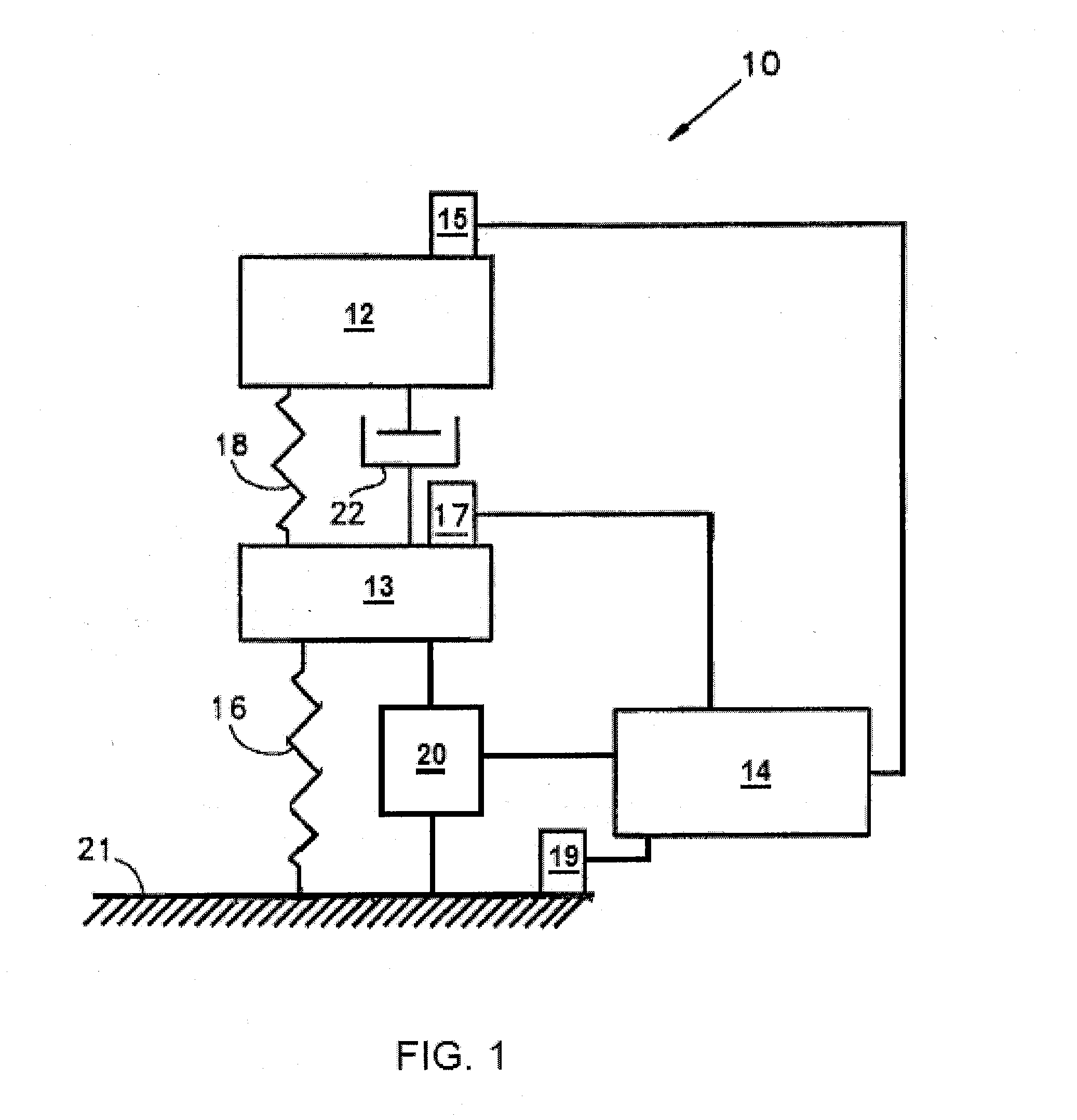
[0017]FIG. 1 illustrates an active vibration isolation system 10 according to one embodiment of the present invention. Active damping system 10 is positioned between an isolated payload 12 (i.e., isolated payload platform or the payload supported thereon or the combination of the two) and a base 21 (e.g., a source of vibration, such as the floor or external casing) to suppress and isolate vibration and other dynamic forces from being transmitted to the payload 12. It should be appreciated that FIG. 1 illustrates a system which addresses active or dynamic vibration isolation in one of three axes. This simplification has been made for the ease of explanation. However, it should be understood that system 10 is capable of being utilized to permit active vibration isolation up to all six degrees of freedom.

[0018]As used throughout the specification and in the claims with reference to a support element, to support “at least substantially all of the static force” of the payload means that ...


PUM


Abstract

An active damping system for use in connection with a vibration isolation system includes an intermediate mass between a base and an isolated payload. The intermediate mass is supported by at least one support element which also supports at least substantially all of the static forces of the isolated payload. An actuator dampens and isolates dynamic forces acting on the intermediate mass from the isolated payload. The active damping system also includes a payload support element and a passive damping element, both of which are coupled at one end to the payload platform and at an opposite end to the intermediate mass. A sensor is affixed to the intermediate mass to generate a feedback signal to a processor coupled to the actuator.

Description

FIELD OF THE INVENTION[0001]The present invention relates to systems for isolating supported payloads from vibrations, and more particularly, to an active vibration isolation system in which at least substantially all of the static force of a payload is supported by passive support elements.BACKGROUND OF THE INVENTION[0002]Vibration isolation systems suppress vibrations acting on a structure or payload. Passive isolators, such as dampers and absorbers, are mechanical solutions that, while effective, have difficulty suppressing vibrations at low frequencies. Active isolation systems have been developed to suppress vibrations acting on a structure or payload at low frequencies. Generally, active isolation systems measure vibrations at specific locations on a platform bearing a payload and dynamically apply cancellation forces in an equal and opposite direction to suppress the effect of the vibration. The vibrations sensed by these dynamic systems are provided to a processor which acti...

Claims


Application Information

Patent Timeline
Patent Type & Authority Applications(United States)
IPC IPC(8): F16F15/02
CPCG05B19/404G05B2219/41191G05B2219/49048G05B2219/49054F16F15/002F16F15/022
Inventor KRANER, EMILLOPES, ANTONIO
Owner TECHN MFG
Why Eureka
Try Eureka