

Large-deflection microactuators
- Summary
- Abstract
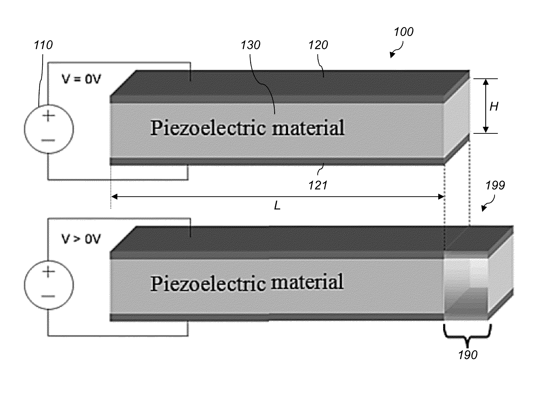
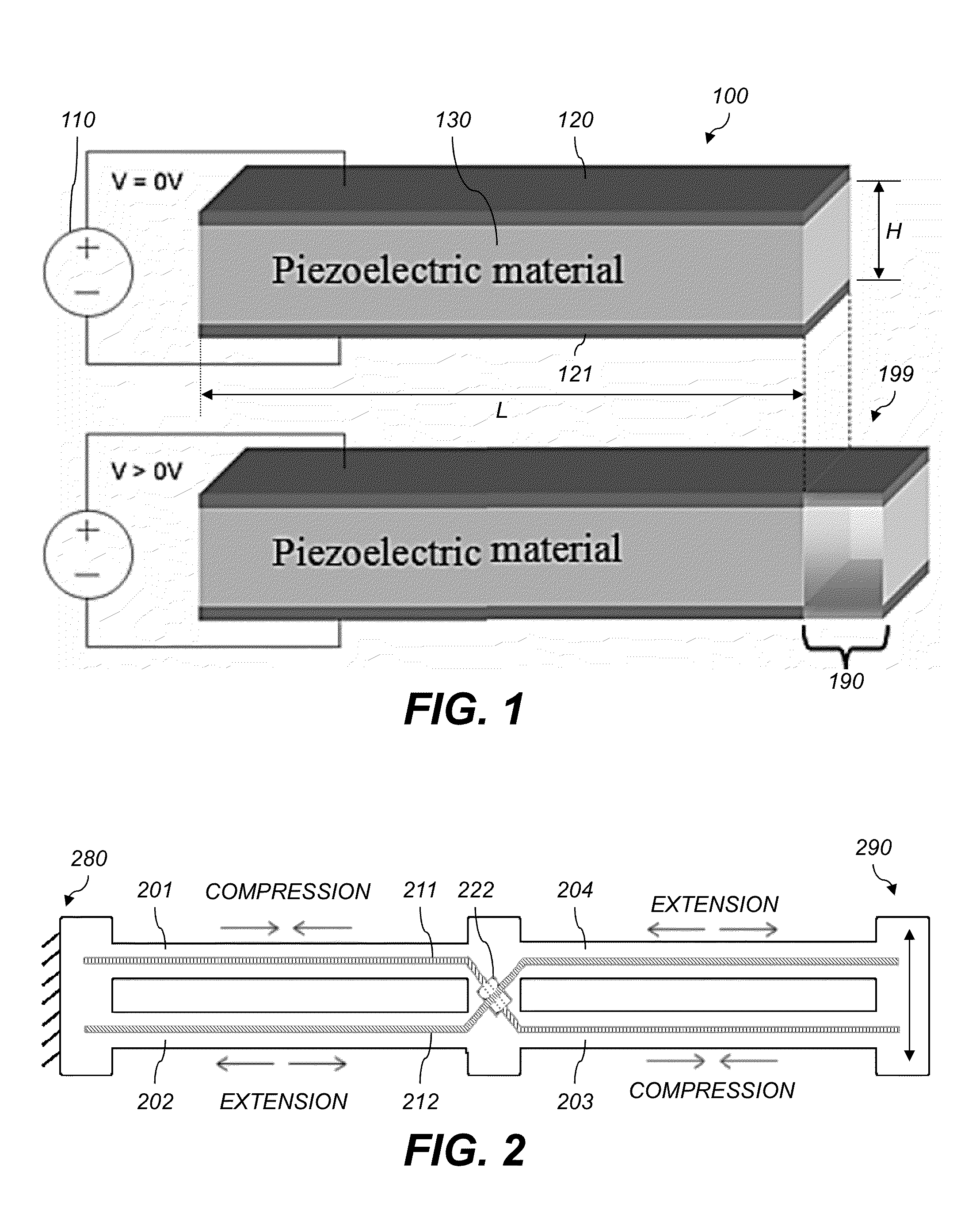
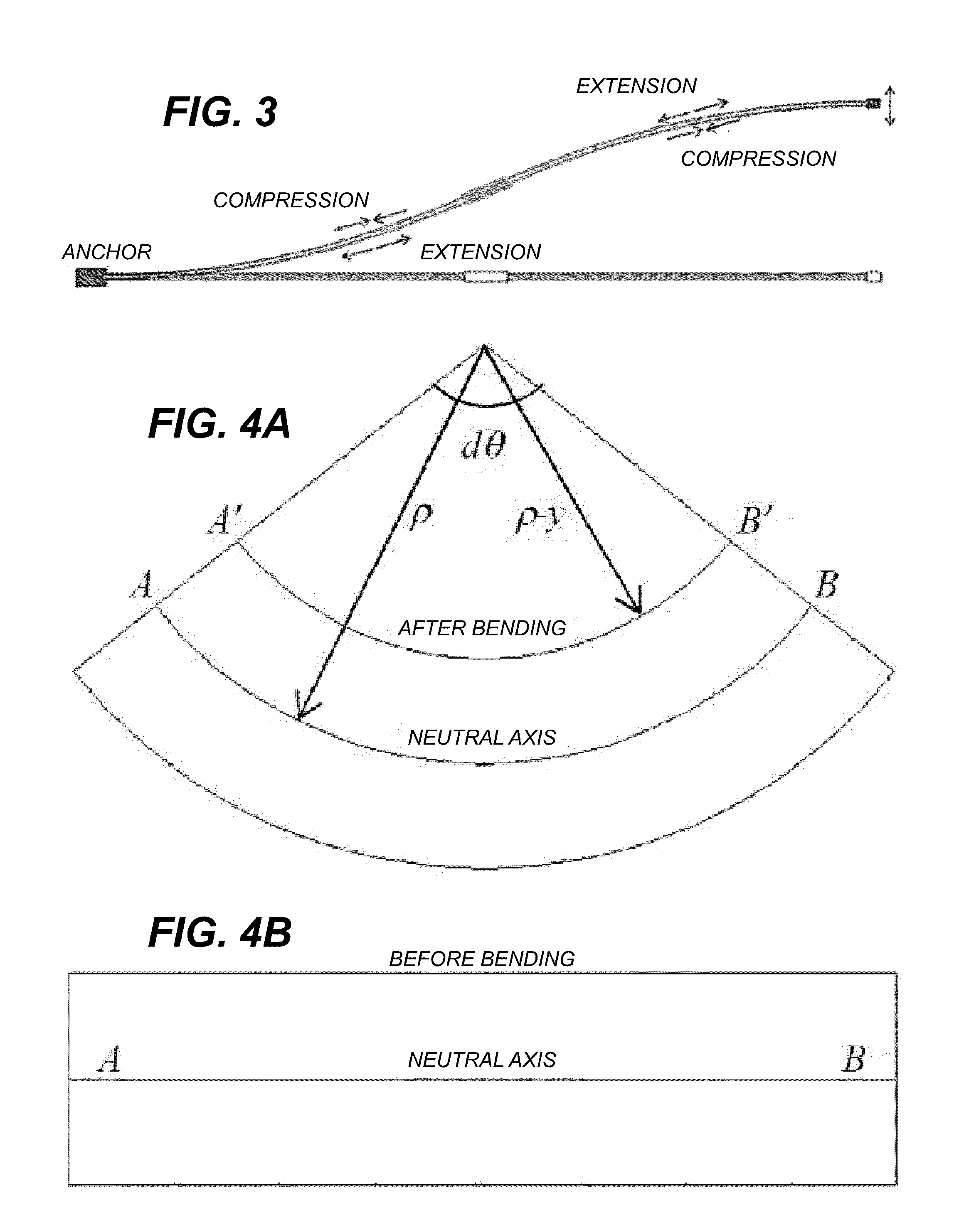
- Description
- Claims
- Application Information
AI Technical Summary
Benefits of technology
Problems solved by technology
Method used
Image

Examples
Embodiment Construction
[0086]Throughout this description, some aspects are described in terms that would ordinarily be implemented as software programs. Those skilled in the art will readily recognize that the equivalent of such software can also be constructed in hardware (hard-wired or programmable), firmware, or micro-code. Accordingly, aspects of the present invention may take the form of an entirely hardware embodiment, an entirely software embodiment (including firmware, resident software, or micro-code), or an embodiment combining software and hardware aspects. Software, hardware, and combinations can all generally be referred to herein as a “service,”“circuit,”“circuitry,”“module,” or “system.” Various aspects can be embodied as systems, methods, or computer program products. Because data manipulation algorithms and systems are well known, the present description is directed in particular to algorithms and systems forming part of, or cooperating more directly with, systems and methods described he...
PUM
 Abstract
Description
Claims
Application Information